
Page 394 - 04. Subyek Engineering Materials - Manufacturing, Engineering and Technology SI 6th Edition - Serope Kalpakjian, Stephen Schmid (2009)
P. 394
Chapter 15 Metal Extrusion and Drawing Processes and Equipment
The major processing variables in drawing are similar to those in extrusion-
that is, reduction in cross-sectional area, die angle, friction along the die-workpiece
interface, and drawing speed. The die angle influences the drawing force and the
quality of the drawn product.
Drawing Force. The expression for the drawing force, F, under ideal and friction-
less conditions is similar to that for extrusion and is given by the equation
A0
P = Y,VgA,1n<Z;>, (15.3)
where Yavg is the average true stress of the material in the die gap. Because more
work has to be done to overcome friction, the force increases with increasing fric-
tion. Furthermore, because of the nonuniform deformation that occurs within the
die zone, additional energy (known as the redundant work of deformation) is re-
quired. Although various equations have been developed to estimate the force (de-
F = Y,,gAf)<1 + %>ln +
scribed in greater detail in advanced texts), a useful formula that includes friction
and the redundant work is A (15.4)
where or is the die angle in radians.
As can be seen from these equations, the drawing force increases as reduction
increases. However, there has to be a limit to the magnitude of the force, because
when the tensile stress reaches the yield stress of the metal being drawn, the work-
piece will simply yield and, eventually, break. It can be shown that, ideally and with-
out friction, the maximum reduction in cross-sectional area per pass is 63%. Thus,
a 10-mm-diameter rod can be reduced (at most) to a diameter of 6.1 mm in one pass
without failure.
It can be shown that, for a certain reduction in diameter and a certain frictional
____ ,,
condition, there is an optimum die angle at which the drawing force is a minimum.
Often, however, the die force is not the major product quality concern, and the actual
die angle may deviate from this value.
F' Di <- _
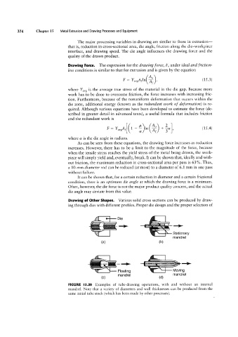
Drawing of Other Shapes. Various solid cross sections can be produced by draw-
ing through dies with different profiles. Proper die design and the proper selection of
at
e*
i (U) Stationary
mandrel
(3)
,
g
Floating
MOVWQ
mandfel
(d)
(C) mandrel if"~ ¢:--I-l"'
FIGURE |5.20 Examples of tube-drawing operations, with and without an internal
mandrel. Note that a variety of diameters and wall thicknesses can be produced from the
same initial tube stock (which has been made by other processes).