
Page 396 - 04. Subyek Engineering Materials - Manufacturing, Engineering and Technology SI 6th Edition - Serope Kalpakjian, Stephen Schmid (2009)
P. 396
376 Chapter 15 Metal Extrusion and Drawing Processes and Equipment
Entering ang|e cally conductive textiles, filter media, radar camouflage, and med-
Drawing been developed to produce fine wire that is broken or chopped into
direction various sizes and shapes. These wires are then used in applications
such as electrically conductive plastics, heat-resistant and electri-
ical implants. The wires produced can be as small as 4 /.tm in
xgge-
diameter and can be made from such materials as stainless steels,
‘X
af.; ff Q as *> if Approach angle titanium, and high-temperature alloys.
Bearing surface (land)
a.
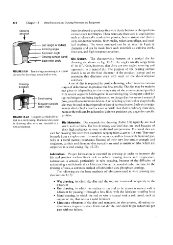
The characteristic features of a typical die for
Die Design.
Back relief angle
drawing are shown in Fig. 15.21. Die angles usually range from
6° to 15°. Note, however, that there are two angles (entering and
approach) in a typical die. The purpose of the bearing surface
FIGURE l5.2I Terminology pertaining to a typical (land) is to set the final diameter of the product (sizing) and to
die used for drawing a round rod or wire. maintain this diameter even with wear on the die-workpiece
interface.
A set of dies is required for profile drawing, which involves various
Drawing stages of deformation to produce the final profile. The dies may be made in
diV9CiiOH
»f" __ Afff Stee| Casing one piece or (depending on the complexity of the cross-sectional profile)
E
__
with several segments held together in a retaining ring. Computer-aided de-
,_
sign techniques are being implemented to design dies for smooth material
also may be used in drawing rods or bars of various shapes. Such an arrange-
ment (called a Tm'/<’s bead) is more versatile than that in ordinary draw dies,
,... I_US;§§t(?_T5arb'de flow, as well as to minimize defects. A set of idling cylindrical or shaped rolls
because the rolls can be adjusted to different positions and angles for specific
profiles.
FIGURE |5.22 Tungsten-carbide die in-
sert in a steel casing. Diamond dies used
in drawing thin Wire are encased in a Die Materials. Die materials for drawing (Table 5.8) typically are tool
similar manner. steels and carbides. For hot drawing, cast-steel dies are used because of
their high resistance to wear at elevated temperatures. Diamond dies are
used for drawing fine wire with diameters ranging from 2 /,tm to 1.5 mm. They may
be made from a single-crystal diamond or in polycrystalline form with diamond par-
ticles in a metal matrix (compacts). Because of their very low tensile strength and
toughness, carbide and diamond dies typically are used as inserts or nibs, which are
supported in a steel casing (Fig. 1522).
Lubrication. Proper lubrication is essential in drawing in order to improve die
life and product surface finish and to reduce drawing forces and temperature.
Lubrication is critical, particularly in tube drawing, because of the difficulty of
maintaining a sufficiently thick lubricant film at the mandrel-tube interface. In the
drawing of rods, a common method of lubrication uses phosphate coatings.
The following are the basic methods of lubrication used in wire drawing (see
also Section 33.7):
° Wet drawing, in which the dies and the rod are immersed completely in the
lubricant
° Dry drawing, in which the surface of the rod to be drawn is coated with a
lubricant by passing it through a box filled with the lubricant (stuffing box)
° Metal coating, in which the rod or wire is coated with a soft metal, such as
copper or tin, that acts as a solid lubricant
° Ultrasonic vibration of the dies and mandrels; in this process, vibrations re-
duce forces, improve surface finish and die life, and allow larger reductions per
pass without failure.