
Page 397 - 04. Subyek Engineering Materials - Manufacturing, Engineering and Technology SI 6th Edition - Serope Kalpakjian, Stephen Schmid (2009)
P. 397
Section 15.10 Drawing Equipment 3
l5.9 Drawing Defects and Residual Stresses
Typical defects in a drawn rod or wire are similar to those observed in extrusion-
especially center cracking (see Fig. 15.17). Another major type of defect in drawing
is seams, which are longitudinal scratches or folds in the material. Seams may open
up during subsequent forming operations (such as upsetting, heading, thread
rolling, or bending of the rod or wire), and they can cause serious quality-control
problems. Various other surface defects (such as scratches and die marks) also can
result from improper selection of the process parameters, poor lubrication, or poor
die condition.
Because they undergo nonuniform deformation during drawing, cold-drawn
products usually have residual stresses. For light reductions, such as only a few per-
cent, the longitudinal-surface residual stresses are compressive (while the bulk is in
LUbI’lCElI’il app|lCé`lllO|'1
tension) and fatigue life is thus improved. Conversely, heavier reductions induce ten-
sile surface stresses (while the bulk is in compression). Residual stresses can be signif-
icant in causing stress-corrosion cracking of the part over time. Moreover, they cause
the component to warp if a layer of material subsequently is removed (see Fig. 230),
such as by slitting, machining, or grinding.
Rods and tubes that are not sufficiently straight (or are supplied as coil) can be
straightened by passing them through an arrangement of rolls placed at different
axes-a process similar to roller leveling (see Fig. 13.7b).
l5.l0 Drawing Equipment
Although it is available in several designs, the equipment for drawing is basically of
two types: the draw bench and the bull block.
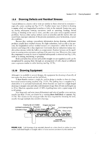
A draw bench contains a single die, and its design is similar to that of a long,
horizontal tension-testing machine (Fig. 1523). The pulling force is supplied by a
chain drive or is activated hydraulically. Draw benches are used for a single-length
drawing of straight rods and tubes with diameters larger than 20 mm and lengths up
to 30 m. Machine capacities reach 1.3 MN of pulling force with a speed range of 6
to 60 m/min.
Very long rods and wire (many kilometers) and wire of smaller cross sections,
usually less than 13 mm, are drawn by a rotating drum (bull block or capstan, Fig.
1524). The tension in this setup provides the force required for drawing the wire,
usually through multiple dies (tandem drawing).
Drawing die and holder Gripper and lever
Reduction / Cgld-drawing trolley
......1 ,D._r.a___Wn Shape ’
Extruded Shape Chain drive
-
_,.iilpmlhh
{0§U01W;)\~V` m i;
s.... X
Direction of drive
FIGURE l5.23 Cold drawing of an extruded channel on a draw bench to reduce its cross
section. Individual lengths of straight rods or of cross sections are drawn by this method.