
Page 393 - 04. Subyek Engineering Materials - Manufacturing, Engineering and Technology SI 6th Edition - Serope Kalpakjian, Stephen Schmid (2009)
P. 393
Section 15.7 The Drawing Process
surfaces of tubes. The tendency for center cracking (a) increases with increasing die
angle, (b) increases with increasing amount of impurities, and (c) decreases with in-
creasing extrusion ratio and friction.
|5.6 Extrusion Equipment
The basic equipment for extrusion is a horizontal hydraulic press (Fig. 15.18, see also
Fig. 14.17d). These presses are suitable for extrusion because the stroke and speed of
the operation can be controlled, depending on the particular
application. They are capable of applying a constant force
over a long stroke. Consequently, long billets can be used,
correspondingly larger extrusions produced per setup, and
the production rate thus increased. Hydraulic presses with a
ram-force capacity as high as 120 MN have been built, partic-
ularly for hot extrusion of large-diameter billets.
Vertical hydraulic presses typically are used for cold
extrusion. They generally have less capacity than those used
for hot extrusion, but they take up less floor space. In addi-
tion to such presses, crank-joint and /enuc/cle-joint mechani-
cal presses are used for cold extrusion and for impact
extrusion to mass-produce small components. Multistage
operations, where the cross-sectional area is reduced in a
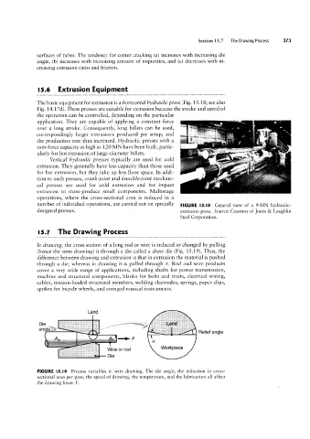
number of individual operations, are carried out on specially FIGURE |5.|8 General view of a 9-MN hydraulic
designed presses. extrusion press. Source: Courtesy of ]ones 85 Laughlin
Steel Corporation.
Die
15.1 The Drawing Process
In drawing, the cross section of a long rod or wire is reduced or changed by pulling
(hence the term drawing) it through a die called a draw die (Fig. 15.19). Thus, the
difference between drawing and extrusion is that in extrusion the material is pushed
through a die, whereas in drawing it is pulled through it. Rod and wire products
cover a very wide range of applications, including shafts for power transmission,
machine and structural components, blanks for bolts and rivets, electrical wiring,
cables, tension-loaded structural members, welding electrodes, springs, paper clips,
spokes for bicycle wheels, and stringed musical instruments.
Die
a“@'@ 'I ara r~srr .., - .., -,...s Relief angie
is
- as . cssts -> F
.
.
FIGURE l5.l9 Process variables in wire drawing. The die angle, the reduction in cross-
sectional area per pass, the speed of drawing, the temperature, and the lubrication all affect
the drawing force, F.