
Page 411 - 04. Subyek Engineering Materials - Manufacturing, Engineering and Technology SI 6th Edition - Serope Kalpakjian, Stephen Schmid (2009)
P. 411
Section 16.2 Shearing
Before After
¢@f Stripper i = Completed
I I
§§=§ ,,§
Die (blank)
Blanking Die (igolsl) apd (D) Scrap
Strip
washer
Pressure Dad
(G)
Ram
punch
PUHCN ul.: T - Piercing
:_
Die -
Scrap 'fc c ere e Y StriDII>9V
Pnot
rrr
1. -iPart
Slug
Stop , _ Si”
_:l
D
Finished Scrap First
washer operation
(C) (Ci)
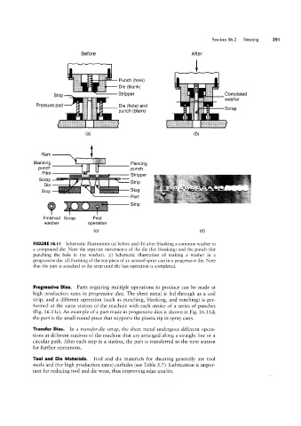
FIGURE l6.l I Schematic illustrations (a) before and (b) after blanking a common washer in
a compound die. Note the separate movements of the die (for blanking) and the punch (for
punching the hole in the washer). (c) Schematic illustration of making a washer in a
progressive die. (d) Forming of the top piece of an aerosol spray can in a progressive die. Note
that the part is attached to the strip until the last operation is completed.
Progressive Dies. Parts requiring multiple operations to produce can be made at
high production rates in progressive dies. The sheet metal is fed through as a coil
strip, and a different operation (such as punching, blanking, and notching) is per-
formed at the same station of the machine with each stroke of a series of punches
(Fig. 16.11c). An example of a part made in progressive dies is shovvn in Fig. 16.11d;
the part is the small round piece that supports the plastic tip in spray cans.
Transfer Dies. ln a transfer-die setup, the sheet metal undergoes different opera-
tions at different stations of the machine that are arranged along a straight line or a
circular path. After each step in a station, the part is transferred to the next station
for further operations.
Tool and Die Materials. Tool and die materials for shearing generally are tool
steels and (for high production rates) carbides (see Table 5.7). Lubrication is impor-
tant for reducing tool and die Wear, thus improving edge quality.