
Page 448 - 04. Subyek Engineering Materials - Manufacturing, Engineering and Technology SI 6th Edition - Serope Kalpakjian, Stephen Schmid (2009)
P. 448
428 Chapter 16 Sheet-Metal Forming Processes and Equipment
l6.l3 Design Considerations in Sheet-metal Formmg
As with most other processes described throughout this book, certain design guide-
lines and practices have evolved with time. Careful design using the best established
design practices, computational tools, and manufacturing techniques is the best ap-
proach to achieving high-quality designs and realizing cost savings. The following
guidelines apply to sheet-metal-forming operations, with the most significant design
issues identified.
Blank Design. Material scrap is the primary concern in blanking operations. (See
also Table 40.6.) Poorly designed parts will not nest properly, and there can be con-
siderable scrap between successive blanking opera-
tions (Fig. 16.55). Some restrictions on blank shapes
are made by the design application, but whenever pos-
sible, blanks should be designed to reduce scrap to a
minimum.
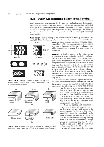
Bending. In bending operations, the main concerns
are material fracture, wrinkling, and the inability to
form the bend. As shown in Fig. 16.56, a sheet-metal
`73`
part with a flange that is to be bent will force the
flange to undergo compression, which can cause buck-
ling (see also Hanging, Section 16.6). This problem
can be controlled with a relief notch cut to limit the
stresses from bending, or else a design modification
as shown in the figure can be made to eliminate the
problem. Right-angle bends have similar difficulties,
and relief notches also can be used to avoid tearing
(Fig. 16.57>.
Because the bend radius is a highly stressed area,
FIGURE l6.55 Efficient nesting of parts for optimum
material utilization in blanking. Source: Courtesy of Society all stress concentrations should be removed from the
of Manufacturing Engineers. bend-radius location. An example is parts with holes
near bends. It is advantageous to move the hole away
from the bend area, but when this is not pos-
Better
Poor `.i.- Best sible, a crescent slot or ear can be used
' tabs and notches should be avoided, since
-`”i E; titr to (Fig. 16.58a). Similarly, in bending flanges,
._ `i~` | g eef , these stress concentrations will greatly re-
large radii should be used to reduce stress
Closed E' 3 X_ melellel Flellel duce formability. When tabs are necessary,
corner thickness (al notch concentration (Fig. 16.58b).
When the bending and production of
...FY
ent the notches properly with respect to the
notches is to be used, it is important to ori-
grain direction. As shown in Fig. 16.17,
bends ideally should be perpendicular to the
rolling direction (or oblique if this is not
C if
Closed corner 3 >< material Relief notch possible) in order to avoid cracking. Bending
thickness sharp radii can be accomplished through
(b) scoring or embossing (Fig. 16.59), but it
should be recognized that this can result
FIGURE l6.56 Control of tearing and buckling of a flange in a right» in fracturing. Burrs should not be present
angle bend. Source: Courtesy of Society of Manufacturing Engineers. in a bend allowance, since they are brittle