
Page 576 - 04. Subyek Engineering Materials - Manufacturing, Engineering and Technology SI 6th Edition - Serope Kalpakjian, Stephen Schmid (2009)
P. 576
Section 21.1 introduction
»
Tool
¢
End mill
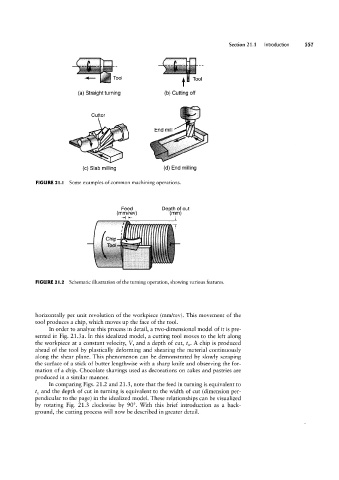
(a) Straight turning (b) Cutting off
Cutter
v/ “Wi
`\ »
(c) Slab milling (d) End milling
FIGURE 2l.l Some examples of common machining operations.
Feed Depth of out
(mm/rev) (mm)
»l l+ r
FIGURE 2|.2 Schematic illustration of the turning operation, showing various features.
horizontally per unit revolution of the workpiece (mm/rev). This movement of the
tool produces a chip, which moves up the face of the tool.
In order to analyze this process in detail, a two-dimensional model of it is pre-
sented in Fig. 21.3a. In this idealized model, a cutting tool moves to the left along
the workpiece at a constant velocity, V, and a depth of cut, to. A chip is produced
ahead of the tool by plastically deforming and shearing the material continuously
along the shear plane. This phenomenon can be demonstrated by slowly scraping
the surface of a stick of butter lengthwise with a sharp knife and observing the for-
mation of a chip. Chocolate shavings used as decorations on cakes and pastries are
produced in a similar manner.
In comparing Figs. 21.2 and 21.3, note that the feed in turning is equivalent to
to and the depth of cut in turning is equivalent to the width of cut (dimension per-
pendicular to the page) in the idealized model. These relationships can be visualized
by rotating Fig. 21.3 clockwise by 90°. With this brief introduction as a back-
ground, the cutting process will now be described in greater detail.