Page 581 - 04. Subyek Engineering Materials - Manufacturing, Engineering and Technology SI 6th Edition - Serope Kalpakjian, Stephen Schmid (2009)
P. 581

Chapter 21  Fundamentals of Machining

                                        A velocity diagram also can be constructed, as shown in Fig. 21.4b, in which,
                                    from trigonometric relationships, we obtain the equation

                                                                V         VS     VL.
                                                                      =       =                       (21.6a)
                                                           cos(q3 A a)   Cosa   sinfjr
                                    where VS is the velocity at which shearing takes place in the shear plane. Note also that
                                                                    = L = i.
                                                                           V
                                                                      t
                                                                  f   tt   V                          (  21.6b l
                                    These velocity relationships will be utilized further in Section 21.3 in describing
                                    power requirements in cutting operations.

                                    2l.2.I Types of Chips Produced in Metal Cutting
                                    The types of metal chips commonly observed in practice and their photomicro-
                                    graphs are shown in Fig. 21.5. The four main types are as follows:
                                                                      i

                                                    "Yi Q   4.          s
                                           Too      Secondary shear zones
                                                              Primary

                                                            Chi P

                                                                 To
                                                                      ,_ W
                                                    2
                                                              ‘: ",
                                                                 `~   ,g

                                                         7%Q`\1~
                                                     li'j*7f_~
                                                   mf? ~~'~;;~~‘#i:>¥§~¢»-,ssc  *_
                                                   Pi;  ~~~ .»   Q?
                                                     ,\  _'§§~..,;"<¢\;.~ >»
                                                   “~»,¢§\\~.-zfr{,
                                                           ./.
                                                                     ,,
                                                                 ‘J
                                                      I


                                      Low
                                      High  s
                                      shear   x                        -
                                      strain  _ Q `»                  -


                                                 (dl                            (9)

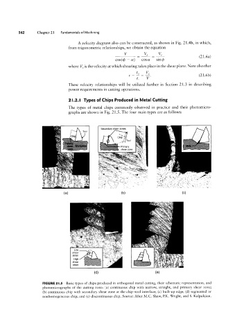
                      FIGURE 2|.5  Basic types of chips produced in orthogonal metal cutting, their schematic representation, and
                      photomicrographs of the cutting zone: (al continuous chip with narrow, straight, and primary shear zone;
                       (b) continuous chip with secondary shear zone at the chip-tool interface; (c) built-up edge; (d) segmented or
                      nonhomogeneous chip; and (e) discontinuous chip. Source: After M.C. Shaw, P.K. Wright, and S. Kalpakjian.
   576   577   578   579   580   581   582   583   584   585   586