
Page 585 - 04. Subyek Engineering Materials - Manufacturing, Engineering and Technology SI 6th Edition - Serope Kalpakjian, Stephen Schmid (2009)
P. 585
Chapter 21 Fundamentals of Machining
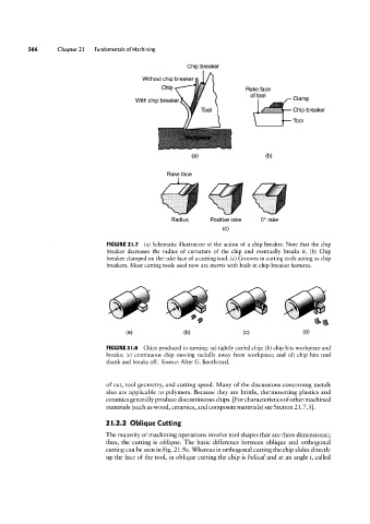
Chip breaker
Chip
Without chip breaker §
With chip breaker Flake face Clamp
of tool
Chip breaker
Tool
(21) (D)
Rake face
Radius Positive rake 0° rake
(C)
FIGURE 2l.'I (a) Schematic illustration of the action of a chip breaker. Note that the chip
breaker decreases the radius of curvature of the chip and eventually breaks it. (b) Chip
breaker clamped on the rake face of a cutting tool. (c) Grooves in cutting tools acting as chip
breakers. Most cutting tools used now are inserts with built-in chip-breaker features.
e g g §
(a) (D) (C) (Ol)
FIGURE 2l.8 Chips produced in turning: (a) tightly curled chip; (b) chip hits workpiece and
breaks; (c) continuous chip moving radially away from workpiece; and (d) chip hits tool
shank and breaks off. Source: After G. Boothroyd.
of cut, tool geometry, and cutting speed. Many of the discussions concerning metals
also are applicable to polymers. Because they are brittle, thermosetting plastics and
ceramics generally produce discontinuous chips. [For characteristics of other machined
materials (such as wood, ceramics, and composite materials) see Section 21.7.3].
2l.2.2 Oblique Cutting
The majority of machining operations involve tool shapes that are three dimensional;
thus, the cutting is oblique. The basic difference between oblique and orthogonal
cutting can be seen in Fig. 21.9a. Whereas in orthogonal cutting the chip slides directly
up the face of the tool, in oblique cutting the chip is helical and at an angle i, called