
Page 588 - 04. Subyek Engineering Materials - Manufacturing, Engineering and Technology SI 6th Edition - Serope Kalpakjian, Stephen Schmid (2009)
P. 588
.
eeee
i i oioo - Tool
Section 21.3
Cutting Forces and Power
1%
(IZ
Q
CNP
oooo F
Tri 'iii
~
oo
- ~""'
ooooo f~'f r ve
-T' ~~~~ ’”‘
4, V
oooo
- -
,,,,
(H) W K,,f,Y, ZVE
(D)
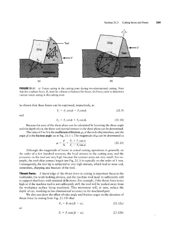
FIGURE 2l.ll (a) Forces acting in the cutting zone during two-dimensional cutting. Note
that the resultant force, R, must be colinear to balance the forces. (b) Force circle to determine
various forces acting in the cutting zone.
be shown that these forces can be expressed, respectively, as
FS = Fccosda - Fzsinda (21.9)
and
Fn = FC sinq5 + F,c0s<;'>. (21.10)
Because the area of the shear plane can be calculated by knowing the shear angle
and the depth of cut, the shear and normal stresses in the shear plane can be determined.
The ratio of F to N is the coefficient of friction, /st, at the tool-chip interface, and the
angle B is the friction angle (as in Fig. 21.1 1). The magnitude of /.L can be determined as
_ 5 _ F, + Fctana
21.11
.
M N Fc - Fttana ( )
Although the magnitude of forces in actual cutting operations is generally on
the order of a few hundred newtons, the local stresses in the cutting zone and the
pressures on the tool are very high because the Contact areas are very small. For ex-
ample, the tool-chip contact length (see Fig. 21.3) is typically on the order of 1 mm.
Consequently, the tool tip is subjected to very high stresses, which lead to wear and,
sometimes, chipping and fracture of the tool.
Thrust Force. A knowledge of the thrust force in cutting is important because the
toolholder, the work-holding devices, and the machine tool must be sufficiently stiff
to support that force with minimal deflections. For example, if the thrust force is too
high or if the machine tool is not sufficiently stiff, the tool will be pushed away from
the workpiece surface being machined. This movement will, in turn, reduce the
depth of cut, resulting in less dimensional accuracy in the machined part.
We also can show the effect of rake angle and friction angle on the direction of
thrust force by noting from Fig. 21.11b that
F, = R sin(B - cr), (21.12a)
or
Ft = FCtan(B - cr). (21.12b)