
Page 587 - 04. Subyek Engineering Materials - Manufacturing, Engineering and Technology SI 6th Edition - Serope Kalpakjian, Stephen Schmid (2009)
P. 587
39?-‘1T0fSh'm
8 Chapter 21 Fundamentals of Machining
Clamp screw
Side-rake
Face
an Ie, + SR) ms?"
9 l Cutting edge Toolholder
Back-rake angle, + (BR)
End-cutting lk
edge angle Side-relief angle
(ECEA) Side-cutting-edge angle (SCEA)
V/ Clearance or end-relief angle
Axis
(H) (D)
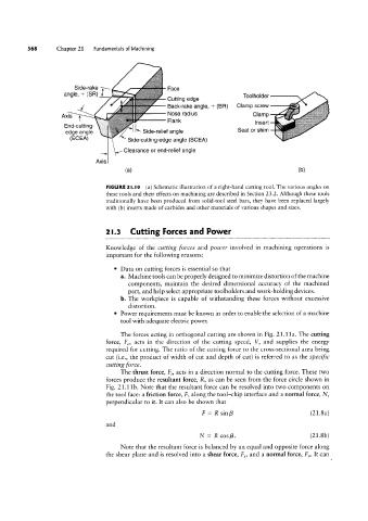
FIGURE 2l.I0 (a) Schematic illustration of a right-hand cutting tool. The various angles on
these tools and their effects on machining are described in Section 23.2. Although these tools
traditionally have been produced from solid-tool steel bars, they have been replaced largely
with (b) inserts made of carbides and other materials of various shapes and sizes.
2l.3 Cutting Forces and Power
Knowledge of the cutting forces and power involved in machining operations is
important for the following reasons:
° Data on cutting forces is essential so that
a. Machine tools can be properly designed to minimize distortion of the machine
components, maintain the desired dimensional accuracy of the machined
part, and help select appropriate toolholders and work-holding devices.
b. The workpiece is capable of withstanding these forces without excessive
distortion.
° Power requirements must be known in order to enable the selection of a machine
tool with adequate electric power.
The forces acting in orthogonal cutting are shown in Fig. 21.11a. The cutting
force, FC, acts in the direction of the cutting speed, V, and supplies the energy
required for cutting. The ratio of the cutting force to the cross-sectional area being
cut (i.e., the product of width of cut and depth of cut) is referred to as the specific
cutting force.
The thrust force, Ft, acts in a direction normal to the cutting force. These two
forces produce the resultant force, R, as can be seen from the force circle shown in
Fig. 21.1lb. Note that the resultant force can be resolved into two components on
the tool face: a friction force, F, along the tool-chip interface and a normal force, N,
perpendicular to it. It can also be shown that
F = R sinB (21.8a)
and
N = R cosB. (21.8b)
Note that the resultant force is balanced by an equal and opposite force along
the shear plane and is resolved into a shear force, FS, and a normal force, F". It can