
Page 586 - 04. Subyek Engineering Materials - Manufacturing, Engineering and Technology SI 6th Edition - Serope Kalpakjian, Stephen Schmid (2009)
P. 586
»
Top view Section 21.2 Mechamcs of Cutting
a
Z
f
Tool
2 "I o -|-00| Cmp
ooo ip
f
Workpiece
X workpiece Chip
(H) (D) (C)
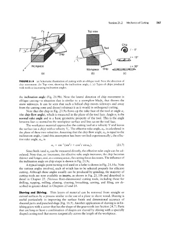
FIGURE 2l.9 (a) Schematic illustration of cutting with an oblique tool. Note the direction of
chip movement. (b) Top view, showing the inclination angle, i. (c) Types of chips produced
with tools at increasing inclination angles.
the inclination angle (Fig. 21.9b). Note the lateral direction of chip movement in
oblique cutting-a situation that is similar to a snowplow blade, that throws the
snow sideways. It can be seen that such a helical chip moves sideways and away
from the cutting zone and doesn’t obstruct it as it would in orthogonal cutting.
Note that the chip in Fig. 21.9a flows up the rake face of the tool at angle ag
(the chip flow angle), which is measured in the plane of the tool face. Angle oz, is the
normal rake angle and is a basic geometric property of the tool. This is the angle
between line oz normal to the workpiece surface and line oa on the tool face.
The workpiece material approaches the cutting tool at a velocity V and leaves
the surface (as a chip) with a velocity VC. The effective rake angle, ae, is calculated in
the plane of these two velocities. Assuming that the chip flow angle, af, is equal to the
inclination angle, i (and this assumption has been verified experimentally), the effec-
tive rake angle, ae, is
ae = sinT1(sin2i + coszi sinan). (21.7)
Since both i and an can be measured directly, the effective rake angle can be cal-
culated. Note that, as i increases, the effective rake angle increases, the chip becomes
thinner and longer, and, as a consequence, the cutting force decreases. The influence of
the inclination angle on chip shape is shown in Fig. 21.9c.
A typical single-point turning tool used on a lathe is shown in Fig. 21.10a. Note
the various angles involved, each of which has to be selected properly for efficient
cutting. Although these angles usually can be produced by grinding, the majority of
cutting tools are now available as inserts, as shown in Fig. 21.1()b and described in
detail in Chapter 22. (Various three-dimensional cutting tools, including those for
drilling, tapping, milling, planing, shaping, broaching, sawing, and filing, are de-
scribed in greater detail in Chapters 23 and 24.
Shaving and Skiving. Thin layers of material can be removed from straight or
curved surfaces by a process similar to the use of a plane to shave wood. Shaving is
useful particularly in improving the surface finish and dimensional accuracy of
sheared parts and punched slugs (Fig. 16.9). Another application of shaving is in fin-
ishing gears with a cutter that has the shape of the gear tooth (see Section 24.7). Parts
that are long or have a combination of shapes are shaved by skit/ing with a specially
shaped cutting tool that moves tangentially across the length of the workpiece.