
Page 579 - 04. Subyek Engineering Materials - Manufacturing, Engineering and Technology SI 6th Edition - Serope Kalpakjian, Stephen Schmid (2009)
P. 579
0 Chapter 21 Fundamentals of Machining
Rake angle,
Chip
Tool (900 _ d) + 01)
V
01) *_
(11) V
(1 /§\ 5
Shear
plane (d, _ U)
0 B
(H) (D)
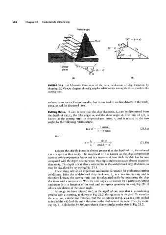
FIGURE 2l.4 (a) Schematic illustration of the basic mechanism of chip formation by
shearing. (b) Velocity diagram showing angular relationships among the three speeds in the
cutting zone.
tan qs =
volume is not in itself objectionable, but it can lead to surface defects in the work-
piece (as will be discussed later).
Cutting Ratio. It can be seen that the chip thickness, tc, can be determined from
the depth of cut, to, the rake angle, a, and the shear angle, d>. The ratio of to/tc is
known as the cutting ratio (or chip-thickness ratio), r, and is related to the two
angles by the following relationships:
1 - 1' sina (21.13)
1 = 5 =3-.
and
tc cos(d> - a) (21.1b>
Because the chip thickness is always greater than the depth of cut, the value of
r is always less than unity. The reciprocal of r is known as the chip-compression
ratio or chip-compression factor and is a measure of how thick the chip has become
compared with the depth of cut; hence, the chip-compression ratio always is greater
than unity. The depth of cut also is referred to as the undeformed chip thickness, as
may be visualized by reviewing Fig. 21.3.
The cutting ratio is an important and useful parameter for evaluating cutting
conditions. Since the undeformed chip thickness, to, is a machine setting and is
therefore known, the cutting ratio can be calculated easily by measuring the chip
thickness with a micrometer. With the rake angle also known for a particular cutting
operation (it is a function of the tool and workpiece geometry in use), Eq. (21.1)
allows calculation of the shear angle.
Although we have referred to to as the depth of cut, note that in a machining
process such as turning, as shown in Fig. 21.2, this quantity is the feed. To visualize
the situation, assume, for instance, that the workpiece in Fig. 21.2 is a thin-walled
tube and the width of the cut is the same as the thickness of the tube. Then, by rotat-
ing Fig. 21.3 clockwise by 90°, note that it is now similar to the view in Fig. 21.2.