Page 577 - 04. Subyek Engineering Materials - Manufacturing, Engineering and Technology SI 6th Edition - Serope Kalpakjian, Stephen Schmid (2009)
P. 577

Chapter 21  Fundamentals of Machining


                                               Rough Surface                           Shiny surface
                                                                                       Rake face
                                                   Chlp                                Tool
                                             Shea'                                     Rake angle
                                                                                       Flank face
                                                                                       Relief or
                                                                                       clearance
                                                                                       angle

                                                                                       Shear angle


                                                                      (H)

                                                                     I


                                               Rough surface
                                                                                       Rake face
                                                                                 1 Tool
                                                  Primary                              Hake angle
                                               shear zone
                                                                                       Flank face


                                                                                       Rough
                                                                                       surface


                                                                   (D)
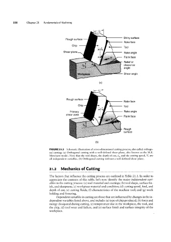
                                   FIGURE 2I.3  Schematic illustration of a two-dimensional cutting process, also called orthogo-
                                   nal cutting: (a) Orthogonal cutting with a well-defined shear plane, also known as the M.E.
                                   Merchant model. Note that the tool shape, the depth of cut, to, and the cutting speed, V, are
                                   all independent variables. (b) Orthogonal cutting without a well-defined shear plane.


                                   2|.2    Mechanics of Cutting


                                   The factors that influence the cutting process are outlined in Table 21.1. In order to
                                   appreciate the contents of this table, let’s now identify the major independent vari-
                                   ables in the cutting process: (a) tool material and coatings; (b) tool shape, surface fin-
                                   ish, and sharpness; (C) workpiece material and condition; (d) cutting speed, feed, and
                                   depth of cut; (e) cutting fluids; (f) characteristics of the machine tool; and (g) work
                                   holding and fixturing.
                                        Dependent variables in cutting are those that are influenced by changes in the in-
                                   dependent variables listed above, and include: (a) type of chip produced, (b) force and
                                   energy dissipated during cutting, (c) temperature rise in the workpiece, the tool, and
                                   the chip, (d) tool wear and failure, and (e) surface finish and surface integrity of the
                                   workpiece.
   572   573   574   575   576   577   578   579   580   581   582