
Page 578 - 04. Subyek Engineering Materials - Manufacturing, Engineering and Technology SI 6th Edition - Serope Kalpakjian, Stephen Schmid (2009)
P. 578
Section 21.2 Mechanics of Cutting
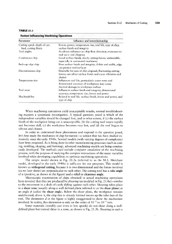
TABLE 2l.l
Factors Influencing Machining Dperaticns
Parameter Influence and interrelationship
Cutting speed, depth of cut, Forces, power, temperature rise, tool life, type of chip,
feed, cutting fluids surface finish and integrity
Tool angles As above; influence on chip flow direction; resistance to
tool wear and chipping
Continuous chip Good surface finish; steady cutting forces; undesirable,
especially in automated machinery
Built-up edge chip Poor surface finish and integrity; if thin and stable, edge
can protect tool surfaces
Discontinuous chip Desirable for ease of chip disposal; fluctuating cutting
forces; can affect surface finish and cause vibration and
chatter
Temperature rise Influences tool life, particularly crater wear and
dimensional accuracy of workpiece; may cause
thermal damage to workpiece surface
Tool wear Influences surface finish and integrity, dimensional
accuracy, temperature rise, forces and power
Machinability Related to tool life, surface finish, forces and power, and
type of chip
When machining operations yield unacceptable results, normal troubleshoot
ing requires a systematic investigation. A typical question posed is which of the
independent variables should be changed first, and to what extent, if (a) the surface
finish of the workpiece being cut is unacceptable, (b) the cutting tool wears rapidly
and becomes dull, (c) the workpiece becomes very hot, and (d) the tool begins to
vibrate and chatter.
In order to understand these phenomena and respond to the question posed,
let’s first study the mechanics of chip formation-a subject that has been studied ex-
tensively since the early 1940s. Several models (with varying degrees of complexity)
have been proposed. As is being done in other manufacturing processes (such as cast-
ing, molding, shaping, and forming), advanced machining models are being continu-
ously developed. The methods used include computer simulation of the machining
process, with the purpose of studying the complex interactions of the many variables
involved while developing capabilities to optimize machining operations.
The simple model shown in Fig. 21.3a (referred to as the M.E. Merchant
model, developed in the early 1940s) is sufficient for our purposes. This model is
known as orthogonal cutting, because it is two dimensional and the forces involved
(as we later show) are perpendicular to each other. The cutting tool has a rake angle
of oz (positive, as shown in the figure) and a relief or clearance angle.
Microscopic examination of chips obtained in actual machining operations
have revealed that they are produced by shearing (as modeled in Fig. 21.4a)-similar
to the movement in a deck of cards sliding against each other. Shearing takes place
in a shear zone (usually along a well-defined plane referred to as the shear plane) at
an angle da (called the shear angle). Below the shear plane, the workpiece remains
undeformed; above it, the chip that is already formed moves up the rake face of the
tool. The dimension d in the figure is highly exaggerated to show the mechanism
involved. In reality, this dimension is only on the order of 10% to 10`3 mm.
Some materials (notably cast irons at low speeds) do not shear along a well-
defined plane but instead shear in a zone, as shown in Fig. 2l.3b. Shearing in such a