
Page 638 - 04. Subyek Engineering Materials - Manufacturing, Engineering and Technology SI 6th Edition - Serope Kalpakjian, Stephen Schmid (2009)
P. 638
Section 23.2 The Turning Process
TABLE 23.2
General Recommendations for Ton! Angles in Turning
High-speed steel Carbide inserts
Back Side End Side Side and end Back Side End Side Side and end
Material rake rake relief relief cutting edge rake rake relief relief cutting edge
Aluminum and 20 15 12 10 5 0 5 5
magnesium alloys
Copper alloys 5 10 8 8 5 0 5 5
Steels 10 12 5 5 15 -5 -5 5
Stainless steels 5 8-10 5 5 15 -5-0 -5-5 5
High-temperature 0 10 5 5 15 5 0 5
alloys
Refractory alloys 0 20 5 5 5 0 O 5
Titanium alloys 0 5 5 5 15 -5 -5 5
Cast irons 5 10 5 5 15 -5 -5 5
Thermoplastics 0 0 20-30 15-20 10 0 0 20-30 15-20
Thermosets 0 0 20-30 15-20 10 0 15 5 5
End view Side view Top view
Side rake Back rake
Tgle (RA) angle SBRA) End cutting-edge
,K 5 ~ ` lp y," H ng (/,\ ) Fiake face
Ie ECEA
5; yi.i»
,,
if "
_
pr, I
J*
N
If
iosiy 1 1 ;§`i,,g%d9ee reir ; §*”#@f*1i< erer, , ,a§§§ -
T ifiii itier irtr T gagfgff
rerir l ieri
F'a"" face
side relief End relief iiiiilii if S Side cuTting-edge K
angie (SCE/-\>
angie (SRA) angle (ERA)
(3) (D) (C)
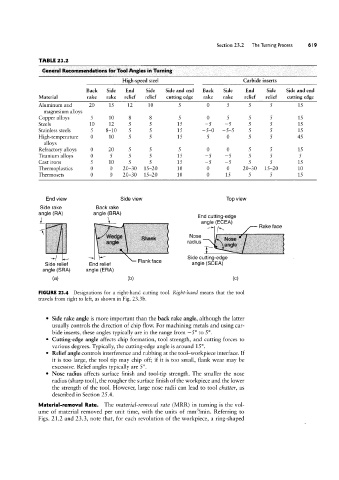
FIGURE 23.4 Designations for a right-hand cutting tool. Right-hand means that the tool
travels from right to left, as shown in Fig. 23.3b.
Side rake angle is more important than the back rake angle, although the latter
usually controls the direction of chip flow. For machining metals and using car-
bide inserts, these angles typically are in the range from -5° to 5°.
Cutting-edge angle affects chip formation, tool strength, and cutting forces to
various degrees. Typically, the cutting-edge angle is around 15°.
Relief angle controls interference and rubbing at the tool-workpiece interface. If
it is too large, the tool tip may chip off; if it is too small, flank wear may be
excessive. Relief angles typically are 5 °.
Nose radius affects surface finish and tool-tip strength. The smaller the nose
radius (sharp tool), the rougher the surface finish of the workpiece and the lower
the strength of the tool. However, large nose radii can lead to tool chatter, as
described in Section 25.4.
Material-removal Rate. The material-removal rate (MRR) in turning is the vol-
ume of material removed per unit time, with the units of mm3/min. Referring to
Figs. 21.2 and 23.3, note that, for each revolution of the workpiece, a ring-shaped