
Page 637 - 04. Subyek Engineering Materials - Manufacturing, Engineering and Technology SI 6th Edition - Serope Kalpakjian, Stephen Schmid (2009)
P. 637
Chapter 23 Machining Processes: Turning and Hole Making
Chuck \ Workpiece ._ i
!
Feed,f Tool
(H) (b)
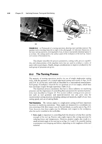
FIGURE 23.3 (a) Photograph of a turning operation, showing insert and chip removal. The
machine tool is traveling from left to right in this photograph. (b) Schematic illustration of
the basic turning operation, showing depth of cut, ci; feed, f; and spindle rotational speed, N,
in rev/min. The cutting speed is the surface speed of the workpiece at the tool tip. Source:
(a) Courtesy of Kennametal Inc.
This chapter describes the process parameters, cutting tools, process capabili-
ties, and characteristics of the machine tools that are used to produce a variety of
parts with round shapes. Finally, design considerations to improve productivity for
each group of processes are given.
23.2 The Turning Process
The majority of turning operations involve the use of simple single-point cutting
tools, with the geometry of a typical right-hand cutting tool shown in Figs. 21.10
and 23.4. As can be seen, such tools are described by a standardized nomenclature.
Each group of workpiece materials has an optimum set of tool angles, which have
been developed largely through experience (Table 23.2).
The important process parameters that have a direct influence on machining
processes and the importance of controlling these parameters for optimized produc-
tivity were described in Chapter 21. This section outlines turning-process parame-
ters such as tool geometry and material-removal rate and gives data for
recommended cutting practices, including cutting-tool materials, depth-of-cut, feed,
cutting speed, and use of cutting fluids.
Tool Geometry. The various angles in a single-point cutting tool have important
functions in machining operations. These angles are measured in a coordinate sys-
tem consisting of the three major axes of the tool shank, as can be seen in Fig. 23.4.
Note, however, that these angles may be different, with respect to the workpiece,
after the tool is installed in the toolholder.
° Rake angle is important in controlling both the direction of chip flow and the
strength of the tool tip. Positive rake angles improve the cutting operation by
reducing forces and temperatures. However, positive angles also result in a
small included angle of the tool tip (as in Figs. 21.3 and 23.4), possibly leading
to premature tool chipping and failure, depending on the toughness of the tool
material.