
Page 639 - 04. Subyek Engineering Materials - Manufacturing, Engineering and Technology SI 6th Edition - Serope Kalpakjian, Stephen Schmid (2009)
P. 639
620 Chapter 23 Machining Processes: Turning and Hole Making
layer of material is removed which has a cross-sectional area that equals the product
of the distance the tool travels in one revolution (feed, f) and the depth of cut, d.
The volume of this ring is the product of the cross-sectional area (f)(d) and the aver-
age circumference of the ring, rrDaVg, where
D, + of
Davg = -‘-iz _
For light cuts on large-diameter workpieces, the average diameter may be replaced
by DO.
The rotational speed of the workpiece is N, and the material removal rate per
revolution is (1-r)(D,,,g)(d)(f Since there are N revolutions per minute, the re-
moval rate is
MRR = ¢fD,,gdfN. <23.1a>
The dimensional accuracy of this equation can be checked by substituting dimen-
sions into the right-hand side. For instance, (mm)(mm)(mm/rev)(rev/min) =
mm3/min, which indicates volume rate of removal. Note that Eq. (23.1a) also can be
written as
MRR = dfV (23.1b)
where V is the cutting speed and MRR has the same unit of mm3/min.
The cutting time, t, for a workpiece of length I can be calculated by noting
that the tool travels at a feed rate of fN = (mm/rev)(rev/min) = mm/min. Since
t = (23.2)
the distance traveled is I mm, the cutting time is
The cutting time in Eq. (23.2) does not include the time required for tool approach
and retraction. Because the time spent in noncutting cycles of a machining operation
is unproductive and adversely affects the overall economics, the time involved in
approaching and retracting tools to and from the workpiece is an important consid-
eration. Machine tools are designed and built to minimize this time. One method of
accomplishing this aim is to rapidly traverse the tools during noncutting cycles, fol-
lowed by a slower movement as the tool engages the workpiece.
The foregoing equations and the terminology used are summarized in Table 23.3.
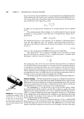
Forces in Turning. The three principal forces acting on a cutting tool are shown in
Fig. 23.5. These forces are important in the design of machine tools, as well as in the
deflection of tools and Workpieces for precision-machining operations. The machine
tool and its components must be able to withstand such forces without causing sig-
nificant deflections, vibrations, and chatter in the overall operation.
‘\ Tool The cutting force, FC, acts downward on the tool tip and thus tends to deflect
Feed, f the tool downward and the workpiece upward. The cutting force supplies the energy
required for the cutting operation, and it can be calculated with the data given in
Table 21.2, from the energy per unit volume, described in Section 21.3. The product
FIGURE 23.5 Forces acting on of the cutting force and its radius from the workpiece center determines the torque
a cutting tool in turning. FC is the on the spindle. The product of the torque and the spindle speed determines the
cutting force, F, is the thrust
power required in the turning operation.
or feed force (in the direction
The thrust force, Ft, acts in the longitudinal direction. It also is called the feed
of feed), and F, is the radial
force, because it is in the feed direction of the tool. This force tends to push the tool
force that tends to push the tool
away from the workpiece being towards the right and away from the chuck. The radial force, F,, acts in the radial
machined. direction and tends to push the tool away from the workpiece. Because of the many