
Page 88 - 04. Subyek Engineering Materials - Manufacturing, Engineering and Technology SI 6th Edition - Serope Kalpakjian, Stephen Schmid (2009)
P. 88
Section 2.4 Torsion 67
Furthermore, friction dissipates energy, so the compressive force is higher than it
otherwise would be in order to supply the work required to overcome friction. With
effective lubrication, friction can be minimized, and a reasonably constant cross-
sectional area can be maintained during the test.
When the results of compression and tension tests on ductile metals are com-
pared, it can be seen that the true stress-true strain curves coincide. This behavior
does not hold true for brittle materials, which are generally stronger and more duc-
tile in compression than in tension. (See Table 8.1.)
When a metal is subjected to tension into the plastic range, and then the load is
released and a compressive load is applied, the yield stress in compression is found to
be lower than that in tension. This phenomenon is known as the Bauschinger effect
(after ]. Bauschinger, who reported it in 1881), and it is exhibited in varying degrees
by all metals and alloys. Because of the lowered yield stress in the direction opposite
that of the original load application, the phenomenon is also called strain softening
ting (Section 21.2). The test method generally used to
or work softening.
determine properties of materials in shear is the torsion
Disk Test. For brittle materials such as ceramics and glasses (Chapter 8), a disk test P
has been developed, in which the disk is subjected to compression between two hard-
ened flat platens (Fig. 2.9). When the material is loaded as shown, tensile stresses
develop perpendicular to the vertical centerline along the disk; fracture begins and
the disk splits in half vertically. The tensile stress, 0, in the disk is uniform along the
centerline and can be calculated from the formula Fracture
0' - E, (2.10)
2P
where P is the load at fracture, cl is the diameter of the disk, and t is its thickness. In P
order to avoid premature failure at the contact points, thin strips of soft metal are
placed between the disk and the platens. These strips also protect the platens from FIGURE 2.9 Disk test on a
being damaged during the test. The fracture at the center of the specimen has been brittle material, showing the
utilized in the manufacture of seamless tubing (Section 13.6). direction of loading and the
fracture path.
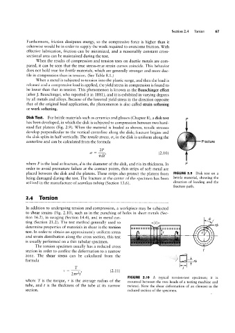
2.4 Torsion
In addition to undergoing tension and compression, a workpiece may be subjected
to shear strains (Fig. 2.1O), such as in the punching of holes in sheet metals (Sec-
tion 16.2), in swaging (Section 14.4), and in metal cut- ->| /|<- Q5 r(1)
The torsion specimen usually has a reduced cross V
=======
========
test. In order to obtain an approximately uniform stress if gg'
and strain distribution along the cross section, this test ` `
is usually performed on a thin tubular specimen.
section in order to confine the deformation to a narrow t
U
zone. The shear stress can be calculated from the _ ..,§.\ 'T _L
formula _F nb
1' = T1 (2.11) lT’l
T
2117215
FIGURE 2.l0 A typical torsion-test specimen; it is
where T is the torque, 1' is the average radius of the mounted between the two heads of a testing machine and
tube, and t is the thickness of the tube at its narrow twisted. Note the shear deformation of an element in the
section. reduced section of the specimen.