
Page 89 - 04. Subyek Engineering Materials - Manufacturing, Engineering and Technology SI 6th Edition - Serope Kalpakjian, Stephen Schmid (2009)
P. 89
68 Chapter 2 Mechanical Behavior, Testing, and Manufacturing Properties of Materials
The shear strain can be calculated from the formula
V = g, (212)
where I is the length of tube subjected to torsion and d> the angle of twist in radians.
The ratio of the shear stress to the shear strain in the elastic range is known as the
shear modulus, or modulus of rigidity, G, a quantity related to the modulus of elastic-
ity, E. The angle of twist, gb, to fracture in the torsion of solid round bars at elevated
temperatures is also useful in estimating the forgeability of metals. The greater the
number of twists prior to failure, the better is the forgeability (Section 14.5 ).
2.5 Bending (Flexure)
Preparing specimens from brittle materials, such as ceramics and carbides, is difficult
because of the problems involved in shaping and machining them to proper dimen-
sions. Furthermore, such specimens are sensitive to surface defects and notches, and
clamping brittle test specimens for testing is difficult. Also, improper alignment of the
test specimen may result in a nonuniform stress distribution along the cross section.
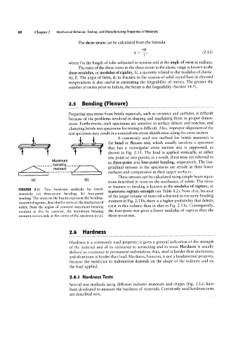
A commonly used test method for brittle materials is
the bend or flexure test, which usually involves a specimen
that has a rectangular cross section and is supported, as
shown in Fig. 2.11. The load is applied vertically, at either
one point or two points; as a result, these tests are referred to
Maximum as three-point and four-point bending, respectively. The lon-
_______ bending_____ gitudinal stresses in the specimens are tensile at their lower
|'T10fT16|'1t
surfaces and compressive at their upper surfaces.
These stresses can be calculated using simple beam equa-
(H) (b) tions described in texts on the mechanics of solids. The stress
at fracture in bending is known as the modulus of rupture, or
FIGURE 2.l I Two bend-test methods for brittle transverse rupture strength (see Table 8.2). Note that, because
materials: (a) three-point bending; (b) four-point of the larger volume of material subjected to the same bending
bending. The areas on the beams represent the bending-
moment diagrams, described in texts on the mechanics of moment in Fig, 2.11b, there is a higher probability that defects
solids. Note the region of constant maximum bending exist in this volume than in that in Fig. 2.11a. Consequently,
moment in (b); by contrast, the maximum bending the four-point test gives a lower modulus of rupture than the
moment occurs only at the center of the specimen in (a). three-point test.
2.6 Hardness
Hardness is a commonly used property; it gives a general indication of the strength
of the material and of its resistance to scratching and to wear. Hardness is usually
defined as resistance to permanent indentation; thus, steel is harder than aluminum,
and aluminum is harder than lead. Hardness, however, is not a fundamental property,
because the resistance to indentation depends on the shape of the indenter and on
the load applied.
2.6.l Hardness Tests
Several test methods using different indenter materials and shapes (Fig. 2.12) have
been developed to measure the hardness of materials. Commonly used hardness tests
are described next.