
Page 90 - 04. Subyek Engineering Materials - Manufacturing, Engineering and Technology SI 6th Edition - Serope Kalpakjian, Stephen Schmid (2009)
P. 90
,5’,,;;;;:¢;<::~::» ., Section 2.6 Hardness
A”
Test
za/
,.
spec|men mas;-ag, Indemou
'ndemor
C°""°'
Pane'
(H) (D)
IE
SI
I/*_
$55.5
w
5?
(C)
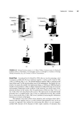
FIGURE 2.l2 Selected hardness testers. (a) A Micro Vickers hardness tester; (b) Rockwell
hardness tester; (c) Durometer; (d) Leeb tester. Source: (a) through (c) Courtesy of Newage
Testing Instruments, Inc.; (d) Courtesy of \X/ilson® Instruments.
Brinell Test. Introduced by ].A. Brinell in 1900, this test involves pressing a steel
or tungsten-carbide ball 10 mm in diameter against a surface, with a load of 500,
1500, or 3000 kg (Fig. 2.13). The Brinell hardness number (I-IB) is defined as the
ratio of the load P to the curved surface area of the indentation. The harder the ma-
terial to be tested, the smaller the impression; hence, a 1500-kg or 3000-kg load is
usually recommended in order to obtain impressions sufficiently large for accurate
measurement. Depending on the condition of the material, one of two types of im-
pression develops on the surface after the performance of this test (Fig. 2.14) or of
any of the other tests described in this section. The impressions in annealed metals
generally have a rounded profile (Fig. 2.14a); in cold-Worked metals, they usually
have a sharp profile (Fig. 2.14b). The correct method of measuring the indentation
diameter, cl, is shovvn in the figure.
The indenter, which has a finite elastic modulus, also undergoes elastic defor-
mation under the applied load; as a result, hardness measurements may not be as
accurate as expected. One method for minimizing this effect is to use tungsten-
carbide balls (Section 22.4); because of their higher modulus of elasticity, they