
Page 201 - Marine Structural Design
P. 201
Chapter 9 Buckling and Local Buckling of Tubular Members 177
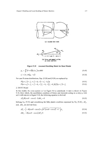
(a) Assumed dent mode
6 -11 ( cos o - cos a )
(b) Force and rarnt actfng
on cross sections
Figure 9.18 Assumed Buckling Mode for Dent Model
g, = 1 (R + G)(~/O,)~~~&I~ (9.49)
C: = 2a,Rt(g, -a) (9.50)
For case B stress distributions, Eqs. (9.28) and (9.29) are replaced by:
P(77+f,)=f*+f;'+h, +(c+cI-h,)rl (9.5 1)
&+eJ=f3 +fl+h, +dr, -h3 +v5 +h,)flI/(V+fi)+f6 (9.52)
2. DENT Model
In this model, the cross-section c-c' in Figure 9.8 is considered. A dent is shown in Figure
9.18, from which, the equilibrium condition of forces and moments acting on a strip ij, with
unit width shown in Figure 9.18, the following equation is derived:
AF,R(cos 0 - cosa)- 2AM, = 0 (9.53)
Solving Eq. (9.53) and considering the fully plastic condition expressed by Eq. (9.41), AF,,
and, AM, are derived from:
[
AF, = - R(cos B - cos a)+ dRz (cos0 - cosa>2 + t2 (9.54)
AM^ = R(COS e - COS ~)AF, (9.55)
/2