
Page 206 - Marine Structural Design
P. 206
182 Part II Ultimate Strength
System Analysis
The procedure used for the system analysis using the proposed Idealized Structural Unit is as
follows:
- At each step of the incremental calculation, moment distributions are evaluated in elements
in which axial force is in compression.
- Based on the moment and axial force distribution, the stress is calculated and the yielding
of the element is checked.
- If yielding is detected in an element at a certain step, the initial yielding load of this
element is evaluated. Then, the elasto-plastic analysis is performed using Eqs. (9.69) thru
(9.71) or Eqs. (9.72) thru (9.75) until AP becomes AX,.
In the following steps, the same calculation is performed at each element where plastification
takes place. If dp shows its maximum value dp,, in a certain element before it reaches AX,
at a certain step, this element is regarded to have attained its ultimate strength
+
Pu (= Xi dp,,) . Then, all the increments at this step are multiplied by dP,,/MTi .
For the element that has attained its ultimate strength, its deflection is increased by keeping the
axial force constant until the fully plastic condition is satisfied at the cross-section where the
bending moment is maximum. Then, this element is divided into two elements and a plastic
node is inserted at this cross-section.
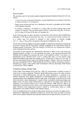
The results of such analyses are schematically illustrated in terms of the axial forces and
bending moments in Figure 9.21. (0) represents the results of the Idealized Structural Unit
Method, and the dashed line represents the results of the simplified method. Up to point 4, no
plastification occurs. Between points 4 and 5, yielding takes place, and the analysis using
simplified methods starts where the yielding occurs. No decrease is observed in this step. At
the next step between points 5 and 6, the ultimate strength is attained. Then, the increment of
this step is multiplied by b5/56. While keeping the axial force constant, the bending moment is
increased up to point c, and a plastic node is introduced. After this, the Plastic Node Method
(Veda and Yao, 1982) is applied.
Evaluation of Strain at Plastic Node
In the Plastic Node Method (Ueda and Yao, 1982), the yield function is defined in terms of
nodal forces or plastic potentials. Therefore, plastic deformation occurs in the form of plastic
components of nodal displacements, and only the elastic deformation is produced in an
element. Physically, these plastic components of nodal displacements are equivalent to the
integrated plastic strain distribution near the nodal point. If the plastic work done by the nodal
forces and plastic nodal displacements is equal to those evaluated by distributed stresses and
plastic strains, the plastic nodal displacements are equivalent to the plastic strain field in the
evaluation of the element stiffness matrix Veda and Fujikabo, 1986). However, there is no
mathematical relationship between plastic nodal displacements and plastic strains at the nodal
point. Therefore, some approximate method is needed to evaluate plastic strain at a nodal
points based on the results of Plastic Node Method analysis.
Here, the internal forces move along the fully plastic interaction curve after the plastic node is
introduced as indicated by a solid line in Figure 9.22. On the other hand, the result of accurate
elasto-plastic analysis using the finite element methods may be represented by a dashed line in