
Page 298 - Marine Structural Design
P. 298
274 Part II Ultimate Strength
(ton)
1200
1000
800
600
400
200
0
Dirplacemrnt hm)
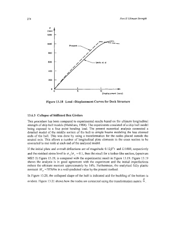
Figure 13.18 Load -Displacement Curves for Deck Structure
13.6.3 Collapse of Stiffened Box Girders
This procedure has been compared to experimental results based on the ultimate longitudinal
strength of ship hull models (Nishihara, 1984). The experiments consisted of a ship hull model
being exposed to a four point bending load. The present numerical analysis connected a
detailed model of the middle section of the hull to simple beams modeling the less stressed
ends of the hull. This was done by using a transformation for the nodes placed outside the
neutral axis. This allows a number of longitudinal plate elements in the cross section to be
connected to one node at each end of the analyzed model.
If the initial plate and overall deflections are of magnitude 0.12PZt and L/ZOOO, respectively
and the residual stress level is cr,/cry = 0.1, then the result for a tanker-like section, (spectrum
MST-3) Figure 13.19, is compared with the experimental result in Figure 13.19. Figure 13.19
shows the analysis is in good agreement with the experiment and the initial imperfections
reduce the ultimate moment approximately by 14%. Furthermore, the analytical filly plastic
moment M, =7871dvm is a well-predicted value by the present method.
In Figure 13.20, the collapsed shape of the hull is indicated and the buckling of the bottom is
s
evident. Figure 13.21 shows how the nodes are connected using the transformation matrix = .