
Page 303 - Marine Structural Design
P. 303
Chapter 13 Collapse Analysis of Ship Hulls 279
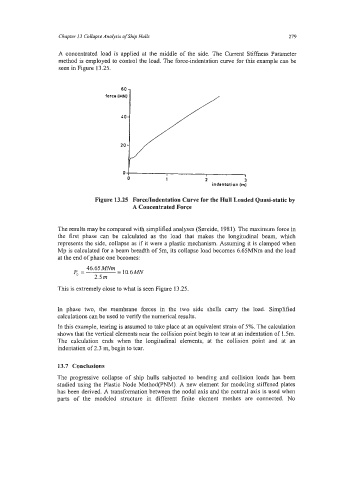
A concentrated load is applied at the middle of the side. The Current Stiffness Parameter
method is employed to control the load. The force-indentation curve for this example can be
seen in Figure 13.25.
60 7
force IMN)
LO-
20 -
0 8 1
1
0 1 2 3
indentation [rn]
Figure 13.25 Force/Indentation Curve for the Hull Loaded Quasi-static by
A Concentrated Force
The results may be compared with simplified analyses (Smeide, 1981). The maximum force in
the first phase can be calculated as the load that makes the longitudinal beam, which
represents the side, collapse as if it were a plastic mechanism. Assuming it is clamped when
Mp is calculated for a beam breadth of 5m, its collapse load becomes 6.65MNm and the load
at the end of phase one becomes:
This is extremely close to what is seen Figure 13.25.
In phase two, the membrane forces in the two side shells carry the load. Simplified
calculations can be used to verify the numerical results.
In this example, tearing is assumed to take place at an equivalent strain of 5%. The calculation
shows that the vertical elements near the collision point begin to tear at an indentation of 1.5m.
The calculation ends when the longitudinal elements, at the collision point and at an
indentation of2.3 m, begin to tear.
13.7 Conclusions
The progressive collapse of ship hulls subjected to bending and collision loads has been
studied using the Plastic Node MethodpNM). A new element for modeling stiffened plates
has been derived. A transformation between the nodal axis and the neutral axis is used when
parts of the modeled structure in different finite element meshes are connected. No