
Page 302 - Marine Structural Design
P. 302
278 Part II Ultimate Strength
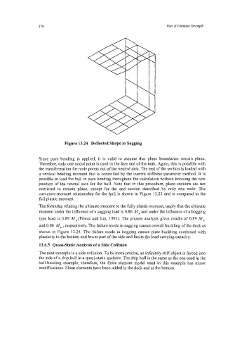
Figure 13.24 Deflected Shape in Sagging
Since pure bending is applied, it is valid to assume that plane boundaries remain plane.
Therefore, only one nodal point is used in the fore end of the tank. Again, this is possible with
the transformation for node points out of the neutral axis. The end of the section is loaded with
a vertical bending moment that is controlled by the current stiffness parameter method. It is
possible to load the hull in pure bending throughout the calculation without knowing the new
position of the neutral axis for the hull. Note that in this procedure, plane sections are not
restricted to remain plane, except for the end section described by only one node. The
curvature-moment relationship for the hull is shown in Figure 13.23 and is compared to the
full plastic moment.
The formulae relating the ultimate moment to the fully plastic moment, imply that the ultimate
moment under the influence of a sagging load is 0.86 M, and under the influence of a hogging
type load is 0.89 M, (Frieze and Lin, 1991). The present analysis gives results of 0.89 M,
and 0.88 MP , respectively. The failure mode in sagging causes overall buckling of the deck as
shown in Figure 13.24. The failure mode in hogging causes plate buckling combined with
plasticity in the bottom and lower part of the side and limits the load carrying capacity.
13.6.5 Quasi-Static Analysis of a Side Collision
The next example is a side collision. To be more precise, an infinitely stiff object is forced into
the side of a ship hull in a quasi-static analysis. The ship hull is the same as the one used in the
hull-bending example; therefore, the finite element model used in this example has minor
modifications. Shear elements have been added in the deck and at the bottom.