
Page 495 - Marine Structural Design
P. 495
Chapter 26 Reliability-Based Design and Code Calibration 47 1
1.18~-1
= 3.72
B=JGi-qxz
Hence,
y= 1.76
Note that the expression for the reliability index p, assuming PR f PS follows log-
normal distribution, may be defined by:
26.5 Numerical Example for Tubular Structure
26.5.1 Case Description
To demonstrate the calibration procedure, a detailed example is given below, which is directly
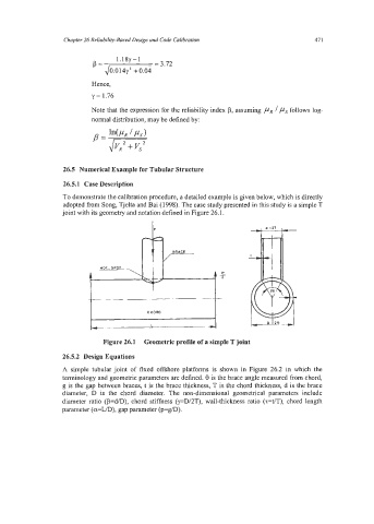
adopted from Song, Tjelta and Bai (1998). The case study presented in this study is a simple T
joint with its geometry and notation defined in Figure 26.1.
Figure 26.1 Geometric profile of a simple T joint
26.5.2 Design Equations
A simple tubular joint of fixed offshore platforms is shown in Figure 26.2 in which the
terminology and geometric parameters are defined. 8 is the brace angle measured from chord,
g is the gap between braces, t is the brace thickness, T is the chord thickness, d is the brace
diameter, D is the chord diameter. The non-dimensional geometrical parameters include
diameter ratio (p=d/D), chord stiffness (y=DIZT), wall-thickness ratio (r=VT), chord length
parameter (a=WD), gap parameter (p=g/D).