
Page 496 - Marine Structural Design
P. 496
472 Part IVStructural Reliability
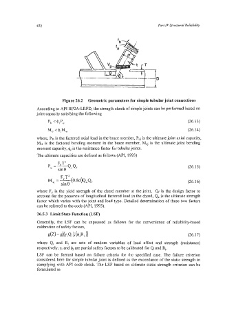
Figure 26.2 Geometric parameters for simple tubular joint connections
According to API RP2A-LRFD, the strength check of simple joints can be performed based on
joint capacity satisfying the following
Po < 4 jP"j (26.13)
Mo < +jM"j (26.14)
where, PD is the factored axial load in the brace member, P,j is the ultimate joint axial capacity,
MD is the factored bending moment in the brace member, M,j is the ultimate joint bending
moment capacity, 4, is the resistance factor for tubularjoints.
The ultimate capacities are defined as follows (API, 1993)
F T2
Q.Qf
sin
8
P"j =y (26.15)
(26.16)
where F, is the yield strength of the chord member at the joint, Qf is the design factor to
account for the presence of longitudinal factored load in the chord, Q,, is the ultimate strength
factor which vanes with the joint and load type. Detailed determination of these two factors
can be referred to the code (API, 1993).
26.5.3 Limit State Function (LSF)
Generally, the LSF can be expressed as follows for the convenience of reliability-based
calibration of safety factors,
dz) = d(YiQi X (4jR j )I (26.17)
where Qi and Rj are sets of random variables of load effect and strength (resistance)
respectively; yi and $j are partial safety factors to be calibrated for Qi and Rj.
LSF can be formed based on failure criteria for the specified case. The failure criterion
considered here for simple tubular joint is defined as the exceedance of the static strength in
complying with API code check. The LSF based on ultimate static strength criterion can be
formulated as