
Page 620 - Marine Structural Design
P. 620
596 Part V Risk Assessment
several functions for each operating mode. The essential functions are often obvious and easy
to establish, while the other functions may be rather difficult to reveal.
The identified system functions may then be represented by functional diagrams of various
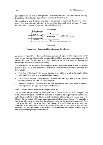
types. The most common diagram is the so-called functional block diagram. A simple
functional block diagram of a pump is shown in Figure 34.3.
.
I
Fluid in I I
I Fluid Out
I a
Figure 34.3 Functional Block Diagram for a Pump
As shown in Figure 34.3, a functional diagram includes all inputs (control signals and power
supplies) and outputs. It is generally not required to establish functional block diagrams for all
system functions. The diagrams are, often considered as efficient tools to illustrate the
input/output interfaces of a system boundary.
The last task of the functional failure analysis is to identify and describe how the system
bctions may fail. In most of the RCM references, functional failures may be classified into
three groups:
Total loss of function: In this case, a function is not achieved at all, or the quality of the
function is far beyond what is considered acceptable.
Partial loss of function: This group may be very broad, and may range fkom the nuisance
category to almost the total loss of the function.
Erroneous function: This means that the item performs an action that was not intended,
often it performs the opposite of the intended function.
Step 3: Failure Modes and Effects Analysis (FMEA)
The dominant failure modes are developed from a failure modes and effect analysis. The
FMEA identified specific conditions that need to be prevented by preemptive maintenance.
After having defined system functions and hctional failures, the next logical step is to
identify failure modes, which may cause each identified functional failure. For example, a
functional failure analysis identified that a booster pump was designed to increase water from
5 bar at the inlet to 25 bar at the outlet. Sometimes it is not able to deliver water to 25 bar.
Therefore, it has a functional failure - partial loss of function. In the FMECA step, the tasks
are to find out what may cause this functional failure and what maintenance methods may be
cost-effective enough to prevent the failure.