Page 123 - Marks Calculation for Machine Design
P. 123

P1: Sanjay
                          January 4, 2005
                                      16:18
        Brown.cls
                 Brown˙C02
                              U.S. Customary     BEAMS            SI/Metric       105
                    Step 2. The couple (C B ) is given by  Step 2. The couple (C B ) is given by
                         C B =−Fb =−(150 lb)(5ft)          C B =−Fb =−(700 N)(1.5m)
                            =−750 ft · lb                     =−1,050 N · m
                     Notethattheminussignmeansitisclockwise  Notethattheminussignmeansitisclockwise
                    (cw).                              (cw).
                                               F
                                      a                    b
                             A                                            B


                                                   L
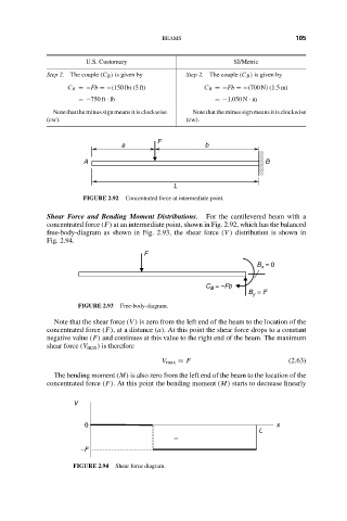
                             FIGURE 2.92  Concentrated force at intermediate point.

                    Shear Force and Bending Moment Distributions.  For the cantilevered beam with a
                    concentrated force (F) at an intermediate point, shown in Fig. 2.92, which has the balanced
                    free-body-diagram as shown in Fig. 2.93, the shear force (V ) distribution is shown in
                    Fig. 2.94.
                                            F
                                                                        B  = 0
                                                                         x

                                                           C  = –Fb
                                                             B
                                                                      B y  = F
                            FIGURE 2.93  Free-body-diagram.
                      Note that the shear force (V ) is zero from the left end of the beam to the location of the
                    concentrated force (F), at a distance (a). At this point the shear force drops to a constant
                    negative value (F) and continues at this value to the right end of the beam. The maximum
                    shear force (V max ) is therefore
                                                 V max = F                      (2.63)
                      The bending moment (M) is also zero from the left end of the beam to the location of the
                    concentrated force (F). At this point the bending moment (M) starts to decrease linearly

                           V

                             0                                               x
                                                                         L
                                                    –
                            –F

                          FIGURE 2.94  Shear force diagram.
   118   119   120   121   122   123   124   125   126   127   128