
Page 125 - Marks Calculation for Machine Design
P. 125
P1: Sanjay
16:18
January 4, 2005
Brown.cls
Brown˙C02
U.S. Customary BEAMS SI/Metric 107
Example 3. Calculate and locate the max- Example 3. Calculate and locate the max-
imum shear force (V max ) and the maximum imum shear force (V max ) and the maximum
bending moment (M max ) for the beam of bending moment (M max ) for the beam of
Examples 1 and 2, where Examples 1 and 2, where
F = 150 lb F = 700 N
L = 8ft L = 2.5 m
a = 3 ft, b = 5ft a = 1m, b = 1.5 m
solution solution
Step 1. Calculate the maximum shear force Step 1. Calculate the maximum shear force
(V max ) from Eq. (2.63) as (V max ) from Eq. (2.63) as
V max = F = 150 lb V max = F = 700 N
Step 2. As shown in Fig. 2.94 this maximum Step 2. As shown in Fig. 2.94, this maximum
shear force (V max ) of 150 lb occurs in the region shear force (V max ) of 150 lb occurs in the region
to the right of the force (F). to the right of the force (F).
Step 3. Calculate the maximum bending Step 3. Calculate the maximum bending
moment (M max ) from Eq. (2.65) as moment (M max ) from Eq. (2.65) as
M max = Fb = (150 lb)(5ft) M max = Fb = (700 N)(1.5m)
= 750 ft · lb = 1,050 N · m
Step 4. As shown in Fig. 2.95 this maximum Step 4. As shown in Fig. 2.95, this maximum
bending moment (M max ) of 750 ft · lb is located bending moment (M max ) of 1,050 N · mis
at the right end of the beam, that is at the wall located at the right end of the beam, meaning
support. at the wall support.
F
a b
A B
∆
L
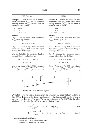
FIGURE 2.96 Beam deflection diagram.
Deflection. For this loading configuration, the deflection ( ) along the beam is shown in
Fig. 2.96, and given by Eq. (2.66a) for the values of the distance (x) from the left end of
the beam to the location of the force (F), at distance (a), and by Eq. (2.66b) for the values
of distance (x) from the force (F) to the right end of the beam.
Fb 2
= (3L − 3 x − b) 0 ≤ x ≤ a (2.66a)
6 EI
F (L − x) 2
= (3 b − L + x) a ≤ x ≤ L (2.66b)
6 EI
where = deflection of beam
F = applied force at intermediate point
x = distance from left end of beam