
Page 130 - Marks Calculation for Machine Design
P. 130
P1: Sanjay
January 4, 2005
16:18
Brown.cls
Brown˙C02
112
STRENGTH OF MACHINES
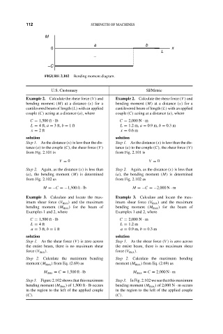
M
a b
0 x
L
–
–C
FIGURE 2.102 Bending moment diagram.
U.S. Customary SI/Metric
Example 2. Calculate the shear force (V ) and Example 2. Calculate the shear force (V ) and
bending moment (M) at a distance (x) for a bending moment (M) at a distance (x) for a
cantilevered beam of length (L) with an applied cantilevered beam of length (L) with an applied
couple (C) acting at a distance (a), where couple (C) acting at a distance (a), where
C = 1,500 ft · lb C = 2,000 N · m
L = 4 ft, a = 3 ft, b = 1ft L = 1.2 m, a = 0.9 m, b = 0.3 m
x = 2ft x = 0.6 m
solution solution
Step 1. As the distance (x) is less than the dis- Step 1. As the distance (x) is less than the dis-
tance (a) to the couple (C), the shear force (V ) tance (a) to the couple (C), the shear force (V )
from Fig. 2.101 is from Fig. 2.101 is
V = 0 V = 0
Step 2. Again, as the distance (x) is less than Step 2. Again, as the distance (x) is less than
(a), the bending moment (M) is determined (a), the bending moment (M) is determined
from Fig. 2.102 as from Fig. 2.102 as
M =−C =−1,500 ft · lb M =−C =−2,000 N · m
Example 3. Calculate and locate the max- Example 3. Calculate and locate the max-
imum shear force (V max ) and the maximum imum shear force (V max ) and the maximum
bending moment (M max ) for the beam of bending moment (M max ) for the beam of
Examples 1 and 2, where Examples 1 and 2, where
C = 1,500 ft · lb C = 2,000 N · m
L = 4ft L = 1.2 m
a = 3 ft, b = 1ft a = 0.9 m, b = 0.3 m
solution solution
Step 1. As the shear force (V ) is zero across Step 1. As the shear force (V ) is zero across
the entire beam, there is no maximum shear the entire beam, there is no maximum shear
force (V max ). force (V max ).
Step 2. Calculate the maximum bending Step 2. Calculate the maximum bending
moment (M max ) from Eq. (2.69) as moment (M max ) from Eq. (2.69) as
M max = C = 1,500 ft · lb M max = C = 2,000 N · m
Step 3. Figure 2.102 shows that this maximum Step 3. In Fig. 2.102 we see that this maximum
bending moment (M max ) of 1,500 ft · lb occurs bending moment (M max ) of 2,000 N · m occurs
in the region to the left of the applied couple in the region to the left of the applied couple
(C). (C).