
Page 133 - Marks Calculation for Machine Design
P. 133
P1: Sanjay
January 4, 2005
16:18
Brown.cls
Brown˙C02
U.S. Customary BEAMS SI/Metric 115
Example 6. Calculate the deflection ( a ) Example 6. Calculate the deflection ( a )
where the couple (C) acts, where where the couple (C) acts, where
C = 1,500 ft · lb C = 2,000 N · m
L = 4ft L = 1.2 m
a = 3 ft, b = 1ft a = 0.9 m, b = 0.3 m
6
6
EI = 2.62 × 10 lb · ft 2 EI = 1.12 × 10 N · m 2
solution solution
Calculate the deflection ( a ) where the couple Calculate the deflection ( a ) where the couple
(C) acts from Eq. (2.72). (C) acts from Eq. (2.72).
Ca 2 Ca 2
a = max =
2 (EI) 2 (EI)
(1,500 ft · lb)(3ft) 2 (2,000 N · m)(0.9m) 2
= =
6
2
2
6
2 (2.62 × 10 lb · ft ) 2 (1.12 × 10 N · m )
3
4
1.35 × 10 lb · ft 3 1.62 × 10 N · m 3
= = 6 2
6
5.24 × 10 lb · ft 2 2.24 × 10 N · m
12 in 100 cm
= 0.0026 ft × = 0.00072 m ×
ft m
= 0.031 in ↓ = 0.072 cm ↓
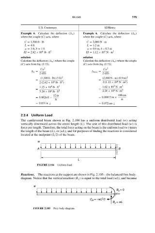
2.3.4 Uniform Load
The cantilevered beam shown in Fig. 2.104 has a uniform distributed load (w) acting
vertically downward across the entire length (L). The unit of this distributed load (w) is
force per length. Therefore, the total force acting on the beam is the uniform load (w) times
the length of the beam (L),or(wL), and for purposes of finding the reactions is considered
located at the midpoint (L/2) of the beam.
w
A B
L
FIGURE 2.104 Uniform load.
Reactions. The reactions at the support are shown in Fig. 2.105—the balanced free-body-
diagram. Notice that the vertical reaction (B y ) is equal to the total load (wL), and because
w
B = 0
x
2
C = –wL /2
B
B = wL
y
FIGURE 2.105 Free-body-diagram.