
Page 131 - Marks Calculation for Machine Design
P. 131
P1: Sanjay
January 4, 2005
Brown˙C02
Brown.cls
A 16:18 BEAMS C B 113
∆
a b
L
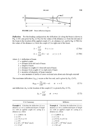
FIGURE 2.103 Beam deflection diagram.
Deflection. For this loading configuration, the deflection ( ) along the beam is shown in
Fig. 2.103, and given by Eq. (2.70a) for the values of the distance (x) from the left end of
the beam to the location of the applied couple (C), at a distance (a), and by Eq. (2.70b) for
the values of the distance (x) from the couple (C) to right end of the beam.
Cx 2
= 0 ≤ x ≤ a (2.70a)
2 EI
Ca
= (2 x − a) a ≤ x ≤ L (2.70b)
2 EI
where = deflection of beam
C = applied couple
x = distance from left end of beam
L = length of beam
a = distance to couple (C) from left end of beam
b = distance from couple (C) to right end of beam
E = modulus of elasticity of beam material
I = area moment of inertia of cross-sectional area about axis through centroid
The maximum deflection ( max ) occurs at the free end, and is given by Eq. (2.67),
Ca
max = (2L − a) at x = L (2.71)
2 EI
and deflection ( a ) at the location of the couple (C) is given by Eq. (2.72),
Ca 2
a = at x = a (2.72)
2 EI
U.S. Customary SI/Metric
Example 4. Calculate the deflection ( ) at a Example 4. Calculate the deflection ( ) at a
distance (x) for a cantilevered beam of length distance (x) for a cantilevered beam of length
(L) with an applied couple (C) acting at a (L) with an applied couple (C) acting at a
distance (a), where distance (a), where
C = 1,500 ft · lb C = 2,000 N · m
L = 4ft L = 1.2 m
a = 3 ft, b = 1ft a = 0.9 m, b = 0.3 m
x = 2ft x = 0.6 m
2
9
2
6
E = 29 × 10 lb/in (steel) E = 207 × 10 N/m (steel)
I = 13 in 4 I = 541 cm 4