
Page 137 - Marks Calculation for Machine Design
P. 137
P1: Sanjay
16:18
January 4, 2005
Brown.cls
Brown˙C02
U.S. Customary BEAMS SI/Metric 119
Step 4. As shown in Fig. 2.109, this maximum Step 4. As shown in Fig. 2.109, this maximum
bending moment (M max ) of 625 ft · lb occurs at bending moment (M max ) of 900 N · m occurs at
the right end of the beam, meaning at the wall the right end of the beam, meaning at the wall
support. support.
w
A B
∆
L
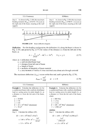
FIGURE 2.110 Beam deflection diagram.
Deflection. For this loading configuration, the deflection ( ) along the beam is shown in
Fig. 2.110, and given by Eq. (2.77) for values of the distance (x) from the left end of the
beam, as
w 4 3 4
= (x − 4L x + 3L ) 0 ≤ x ≤ L (2.77)
24 EI
where = deflection of beam
w = uniform distributed load
x = distance from left end of beam
L = length of beam
E = modulus of elasticity of beam material
I = area moment of inertia of cross-sectional area about axis through centroid
The maximum deflection ( max ) occurs at the free end, and is given by Eq. (2.78),
wL 4
max = at x = 0 (2.78)
8 EI
U.S. Customary SI/Metric
Example 4. Calculate the deflection ( ) for Example 4. Calculate the deflection ( ) for
a cantilevered beam with a uniform distributed a cantilevered beam with a uniform distributed
load (w) acting across its entire length (L),at load (w) acting across its entire length (L), at
a distance (x) from the left end of the beam, a distance (x) from the left end of the beam,
where where
w = 50 lb/ft w = 800 N/m
L = 5ft L = 1.5 m
x = 4ft x = 1.2 m
2
9
6
2
E = 10 × 10 lb/in (aluminum) E = 100 ×10 N/m (aluminum)
I = 36 in 4 I = 1,500 cm 4
solution solution
Step 1. Calculate the stiffness (EI). Step 1. Calculate the stiffness (EI).
4
2
6
2
9
4
EI = (10 × 10 lb/in )(36 in ) EI = (100 × 10 N/m )(1,500 cm )
1ft 2 1m 4
8 2
= 3.60 × 10 lb · in × × 4
144 in 2 (100 cm)
6
6
= 2.5 × 10 lb · ft 2 = 1.5 × 10 N · m 2