
Page 140 - Marks Calculation for Machine Design
P. 140
P1: Sanjay
January 4, 2005
Brown˙C02
Brown.cls
122
U.S. Customary 16:18 STRENGTH OF MACHINES SI/Metric
Step 2. The couple (C B ) is given by Step 2. The couple (C B ) is given by
wL 2 (300 lb/ft)(6ft) 2 wL 2 (4,500 N/m)(1.8m) 2
C B =− =− C B =− =−
6 6 6 6
10,800 ft · lb 14,580 N · m
=− =−1,800 ft · lb =− =−2,430 N · m
6 6
Note that the minus sign on (C B ) means it is Note that the minus sign on (C B ) means it is
clockwise (cw). clockwise (cw).
w
A B
L
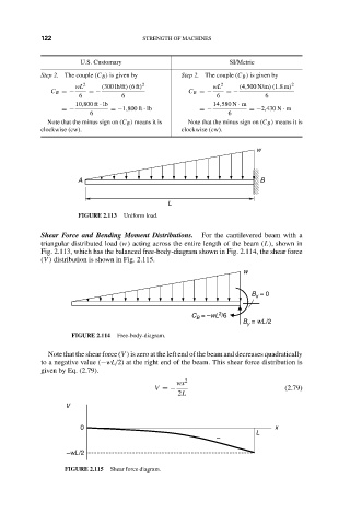
FIGURE 2.113 Uniform load.
Shear Force and Bending Moment Distributions. For the cantilevered beam with a
triangular distributed load (w) acting across the entire length of the beam (L), shown in
Fig. 2.113, which has the balanced free-body-diagram shown in Fig. 2.114, the shear force
(V ) distribution is shown in Fig. 2.115.
w
B = 0
x
2
C = –wL /6
B
B = wL/2
y
FIGURE 2.114 Free-body-diagram.
Note that the shear force (V ) is zero at the left end of the beam and decreases quadratically
to a negative value (−wL/2) at the right end of the beam. This shear force distribution is
given by Eq. (2.79).
wx 2
V =− (2.79)
2L
V
0 x
L
–
–wL/2
FIGURE 2.115 Shear force diagram.