
Page 143 - Marks Calculation for Machine Design
P. 143
P1: Sanjay
16:18
January 4, 2005
Brown.cls
Brown˙C02
BEAMS
L = length of beam
E = modulus of elasticity of beam material 125
I = area moment of inertia of cross-sectional area about axis through centroid
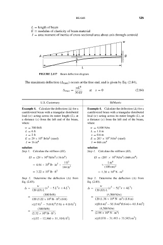
w
A B
∆
L
FIGURE 2.117 Beam deflection diagram.
The maximum deflection ( max ) occurs at the free end, and is given by Eq. (2.84),
wL 4
max = at x = 0 (2.84)
30 EI
U.S. Customary SI/Metric
Example 4. Calculate the deflection ( ) for a Example 4. Calculate the deflection ( ) for a
cantilevered beam with a triangular distributed cantilevered beam with a triangular distributed
load (w) acting across its entire length (L),at load (w) acting across its entire length (L),at
a distance (x) from the left end of the beam, a distance (x) from the left end of the beam,
where where
w = 300 lb/ft w = 4,500 N/m
L = 6ft L = 1.8 m
x = 2ft x = 0.6 m
9
2
2
6
E = 29 × 10 lb/in (steel) E = 207 × 10 N/m (steel)
I = 16 in 4 I = 666 cm 4
solution solution
Step 1. Calculate the stiffness (EI). Step 1. Calculate the stiffness (EI).
4
6
2
4
9
2
EI = (29 × 10 lb/in )(16 in ) EI = (207 × 10 N/m )(666 cm )
1ft 2 1m 4
8 2
= 4.64 × 10 lb · in × 2 × 4
144 in (100 cm)
6
6
= 3.22 × 10 lb · ft 2 = 1.38 × 10 N · m 2
Step 2. Determine the deflection ( ) from Step 2. Determine the deflection ( ) from
Eq. (2.83). Eq. (2.83).
w w
5
5
4
5
4
5
= (x − 5 L x + 4 L ) = (x − 5L x + 4L )
120 (EI) L 120 (EI) L
(300 lb/ft) (4,500 N/m)
= 2 = 6 2
6
120 (3.22 × 10 lb · ft )(6ft) 120 (1.38 × 10 N · m )(1.8m)
4
5
5
4
5
5
×[(2ft) − 5 (6ft) (2ft) + 4 (6ft) ] ×[(0.6m) − 5(1.8m) (0.6m)+4(1.8m) ]
(300 lb/ft) (4,500 N/m)
= = 8 3
3
9
(2.32 × 10 lb · ft ) (2.98 × 10 N · m )
5
5
×[(32 − 12,960 + 31, 104) ft ] ×[(0.078 − 31.493 + 75.583) m ]