
Page 147 - Marks Calculation for Machine Design
P. 147
P1: Rakesh
14:16
January 4, 2005
Brown.cls
Brown˙C03
U.S. Customary ADVANCED LOADINGS SI/Metric 129
Example 2. Determine the maximum inter- Example 2. Determine the maximum inter-
nal gage pressure (p i ) for a spherical steel tank nal gage pressure (p i ) for a spherical steel tank
where the maximum normal stress (σ sph ) is where the maximum normal stress (σ sph ) is
18,000 psi, and where 126 MPa, and where
r m = 6ft = 72 in r m = 2m
t = 0.5 in t = 1.3 cm = 0.013 m
solution solution
Step 1. Solve for the internal pressure (p i ) Step 1. Solve for the internal pressure (p i )
using Eq. (3.1). using Eq. (3.1).
p i r m 2tσ sph p i r m 2tσ sph
σ sph = → p i = σ sph = → p i =
2 t r m 2 t r m
Step 2. Substitute for the thickness (t), the Step 2. Substitute for the thickness (t), the
maximum normal stress (σ sph ), and the mean maximum normal stress (σ sph ), and the mean
radius (r m ) to give radius (r m ) to give
2tσ sph 2tσ sph
p i = p i =
r m r m
2
2
2(0.5in)(18,000 lb/in ) 2 (0.013 m)(126,000,000 N/m )
= =
72 in 2m
18,000 lb/in 3,276,000 N/m
= =
72 in 2m
2
2
= 250 lb/in = 250 psi = 1,638,000 N/m = 1.64 MPa
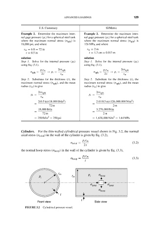
Cylinders. For the thin-walled cylindrical pressure vessel shown in Fig. 3.2, the normal
axial stress (σ axial ) in the wall of the cylinder is given by Eq. (3.2),
p i r m
σ axial = (3.2)
2 t
the normal hoop stress (σ hoop ) in the wall of the cylinder is given by Eq. (3.3),
p i r m
σ hoop = (3.3)
t
r m p s
p r m i hoop
i
s s
axial axial
s hoop
t
t
Front view Side view
FIGURE 3.2 Cylindrical pressure vessel.