
Page 144 - Marks Calculation for Machine Design
P. 144
P1: Sanjay
January 4, 2005
Brown˙C02
Brown.cls
126
U.S. Customary 16:18 STRENGTH OF MACHINES SI/Metric
1 1
5
5
= 1.29 × 10 −7 × (18,176 ft ) = 1.51 × 10 −5 × (44.168 m )
ft 4 m 4
12 in 100 cm
= 0.00235 ft × = 0.00067 m ×
ft m
= 0.028 in ↓ = 0.067 cm ↓
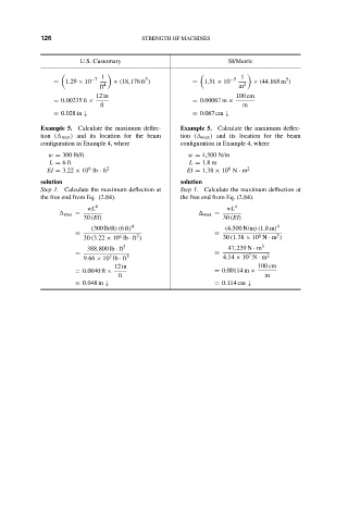
Example 5. Calculate the maximum deflec- Example 5. Calculate the maximum deflec-
tion ( max ) and its location for the beam tion ( max ) and its location for the beam
configuration in Example 4, where configuration in Example 4, where
w = 300 lb/ft w = 4,500 N/m
L = 6ft L = 1.8 m
6
6
EI = 3.22 × 10 lb · ft 2 EI = 1.38 × 10 N · m 2
solution solution
Step 1. Calculate the maximum deflection at Step 1. Calculate the maximum deflection at
the free end from Eq. (2.84). the free end from Eq. (2.84).
wL 4 wL 4
max = max =
30 (EI) 30 (EI)
(300 lb/ft)(6ft) 4 (4,500 N/m)(1.8m) 4
= =
6
2
2
6
30 (3.22 × 10 lb · ft ) 30 (1.38 × 10 N · m )
388,800 lb · ft 3 47,239 N · m 3
= = 7 2
7
9.66 × 10 lb · ft 2 4.14 × 10 N · m
12 in 100 cm
= 0.0040 ft × = 0.00114 m ×
ft m
= 0.048 in ↓ = 0.114 cm ↓