Page 138 - Marks Calculation for Machine Design
P. 138

P1: Sanjay
                          January 4, 2005
                 Brown˙C02
        Brown.cls
                  120
                            U.S. Customary 16:18  STRENGTH OF MACHINES  SI/Metric
                  Step 2. Determine the deflection ( ) from  Step 2. Determine the deflection ( ) from
                  Eq. (2.77).                        Eq. (2.77).
                         w    4    3    4                    w    4    3    4
                      =     (x − 4 L x + 3L )             =     (x − 4 L x + 3L )
                        24 (EI)                            24 (EI)
                            (50 lb/ft)                         (800 N/m)       4
                     =                                   =                [(1.2m)
                                                                        2
                                    2
                                                                    6
                                6
                        24 (2.5 × 10 lb · ft )             24 (1.5 × 10 N · m )
                            4
                                              4
                                                                  3
                                                                               4
                                    3
                       ×[(4ft) − 4 (5ft) (4ft) + 3 (5ft) ]  − 4(1.5m) (1.2m) + 3(1.5m) ]
                            (50 lb/ft)                       (800 N/m)
                       =                                 =
                                                                     2
                                                                 7
                                   2
                              7
                         (6 × 10 lb · ft )                 (3.6 × 10 N · m )
                                                                               4
                                           4
                         × [(256 − 2,000 + 1,875) ft ]     ×[(2.0736 − 16.2 + 15.1875) m ]

                                   1                              −5  1         4

                                            4
                       =  8.33 × 10 −7  × (131 ft )      =  2.22 × 10  3  × (1.0611 m )
                                   ft 3                             m
                                  12 in                              100 cm
                       = 0.00011 ft ×                    = 0.0000235 m ×
                                   ft                                  m
                       = 0.0013 in ↓                     = 0.0024 cm ↓
                  Example 5. Calculate the maximum deflec-  Example 5. Calculate the maximum deflec-
                  tion (  max ) and its location for the beam  tion (  max ) and its location for the beam
                  configuration in Example 4, where   configuration in Example 4, where
                    w = 50 lb/ft                       w = 800 N/m
                    L = 5ft                            L = 1.5 m
                                                                6
                             6
                    EI = 2.5 × 10 lb · ft 2            EI = 1.5 × 10 N · m 2
                  solution                           solution
                  Step 1. Calculate the maximum deflection at  Step 1. Calculate the maximum deflection at
                  the free end from Eq. (2.78).      the free end from Eq. (2.78).
                              wL 4                               wL 4
                          max =                             max =
                              8 (EI)                            8 (EI)
                               (50 lb/ft)(5ft) 4                 (800 N/m)(1.5m) 4
                            =                                 =
                                                                            2
                                         2
                                                                       5
                                     6
                              8 (2.5 × 10 lb · ft )             8 (1.5 × 10 N · m )
                              31,250 lb · ft 3                    4,050 N · m 3
                            =                                 =       7   2
                                  7
                              2 × 10 lb · ft 2                  1.2 × 10 N · m
                                     12 in                               100 cm
                            = 0.0016 ft ×                     = 0.00034 m ×
                                      ft                                   m
                            = 0.019 in ↓                      = 0.034 cm ↓
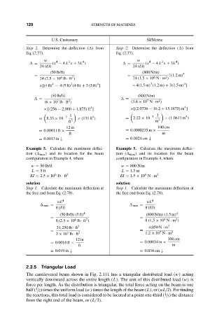
                  2.3.5 Triangular Load
                  The cantilevered beam shown in Fig. 2.111 has a triangular distributed load (w) acting
                  vertically downward across the entire length (L). The unit of this distributed load (w) is
                  force per length. As the distribution is triangular, the total force acting on the beam is one
                      1
                  half ( / 2) times the uniform load (w) times the length of the beam (L),or(wL/2). For finding
                                                                        1
                  the reactions, this total load is considered to be located at a point one-third ( / 3) the distance
                  from the right end of the beam, or (L/3).
   133   134   135   136   137   138   139   140   141   142   143