
Page 120 - Marks Calculation for Machine Design
P. 120
P1: Sanjay
January 4, 2005
Brown˙C02
Brown.cls
102
U.S. Customary 16:18 STRENGTH OF MACHINES SI/Metric
Step 4. As shown in Fig. 2.88, this maximum Step 4. Figure 2.88 shows that this maximum
bending moment (M max ) of 1,200 ft · lb is lo- bending moment (M max ) of 1,750 N · mislo-
cated at the right end of the beam, meaning at cated at the right end of the beam, that is, at the
the wall support. wall support.
F
A B
∆
L
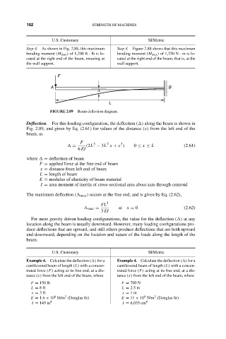
FIGURE 2.89 Beam deflection diagram.
Deflection. For this loading configuration, the deflection ( ) along the beam is shown in
Fig. 2.89, and given by Eq. (2.61) for values of the distance (x) from the left end of the
beam, as
F 3 2 3
= (2L − 3L x + x ) 0 ≤ x ≤ L (2.61)
6 EI
where = deflection of beam
F = applied force at the free end of beam
x = distance from left end of beam
L = length of beam
E = modulus of elasticity of beam material
I = area moment of inertia of cross-sectional area about axis through centroid
The maximum deflection ( max ) occurs at the free end, and is given by Eq. (2.62),
FL 3
max = at x = 0 (2.62)
3 EI
For most gravity driven loading configurations, the value for the deflection ( ) at any
location along the beam is usually downward. However, many loading configurations pro-
duce deflections that are upward, and still others produce deflections that are both upward
and downward, depending on the location and nature of the loads along the length of the
beam.
U.S. Customary SI/Metric
Example 4. Calculate the deflection ( ) for a Example 4. Calculate the deflection ( ) for a
cantilevered beam of length (L) with a concen- cantilevered beam of length (L) with a concen-
trated force (F) acting at its free end, at a dis- trated force (F) acting at its free end, at a dis-
tance (x) from the left end of the beam, where tance (x) from the left end of the beam, where
F = 150 lb F = 700 N
L = 8ft L = 2.5 m
x = 3ft x = 1m
9
2
2
6
E = 1.6 × 10 lb/in (Douglas fir) E = 11 × 10 N/m (Douglas fir)
I = 145 in 4 I = 6,035 cm 4