Page 115 - Marks Calculation for Machine Design
P. 115

P1: Sanjay
                                      16:18
                          January 4, 2005
                 Brown˙C02
        Brown.cls
                              U.S. Customary     BEAMS            SI/Metric        97
                    or at the midpoint of the beam, given by  or at the midpoint of the beam, given by
                    Eq. (2.57),                        Eq. (2.57).
                             wL 2                               wL 2
                                       a
                                                                         a
                    M      =     1 − 4                 M      =     1 − 4
                      max @   8        L                max @    8       L
                      midpoint                          midpoint
                             (15 lb/ft)(12 ft) 2        2ft      (225 N/m)(4m) 2       0.6m
                           =             1 − 4                =            1 − 4
                                  8           12 ft                  8          4m
                                       2
                                                                          2
                             (15 lb/ft)(144 ft )                (225 N/m)(16 m )        3
                                               1
                           =              1 − 4               =              1 − 4
                                  8            6                     8           20
                             2,160 ft · lb     4                3,600 N · m     3
                           =          1 −                     =          1 −
                                8        6                         8        5

                                      1                                  2
                           = (270 ft · lb)                    = (450 N · m)
                                      3                                  5
                           = 90 ft · lb                       = 180 N · m
                      Note that for these relative values of the overhang (a) and the length of the beam (L),
                    the bending moment at the supports is less than the bending moment at the midpoint of the
                    beam. As said earlier, if the overhang (a) is one-fourth the length of the beam (L), that is
                    (a = L/4), then the maximum deflection at the midpoint will be zero, and the maximum
                                                                2
                    bending moment at the supports will have a magnitude of (wL /32).
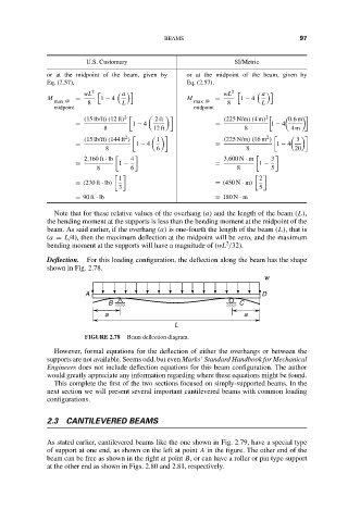
                    Deflection.  For this loading configuration, the deflection along the beam has the shape
                    shown in Fig. 2.78.
                                                                          w
                             A                                           D
                                   B                                C
                                  a                                  a
                                                    L
                             FIGURE 2.78  Beam deflection diagram.
                      However, formal equations for the deflection of either the overhangs or between the
                    supports are not available. Seems odd, but even Marks’ Standard Handbook for Mechanical
                    Engineers does not include deflection equations for this beam configuration. The author
                    would greatly appreciate any information regarding where these equations might be found.
                      This complete the first of the two sections focused on simply-supported beams. In the
                    next section we will present several important cantilevered beams with common loading
                    configurations.

                    2.3 CANTILEVERED BEAMS


                    As stated earlier, cantilevered beams like the one shown in Fig. 2.79, have a special type
                    of support at one end, as shown on the left at point A in the figure. The other end of the
                    beam can be free as shown in the right at point B, or can have a roller or pin type support
                    at the other end as shown in Figs. 2.80 and 2.81, respectively.
   110   111   112   113   114   115   116   117   118   119   120