Page 112 - Marks Calculation for Machine Design
P. 112

P1: Sanjay
                          January 4, 2005
                 Brown˙C02
        Brown.cls
                  94
                          V
                        w(L–2a)/2     16:18  STRENGTH OF MACHINES
                             wa
                                         +                         +
                              0                                               x
                                                                         L
                                    –              L/2        –
                            –wa
                       –w(L–2a)/2
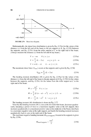
                       FIGURE 2.76  Shear force diagram.
                    Mathematically, the shear force distribution is given by Eq. (2.53a) for the values of the
                  distance (x) from the left end of the beam to the pin support at B, Eq. (2.53b) between
                  the supports, and Eq. (2.53c) from the roller support at C to the right end of the beam.
                  (Always measure the distance (x) from the left end of any beam.)

                                     V =−wx     0 ≤ x ≤ a                     (2.53a)
                                         w
                                     V =   (L − 2 x)  a ≤ x ≤ L − a           (2.53b)
                                         2
                                     V = w(L − x)   L − a ≤ x ≤ L             (2.53c)
                    The maximum shear force (V max ) occurs at the supports and is given by Eq. (2.54)
                                                 w
                                           V max =  (L − 2 a)                  (2.54)
                                                  2
                    The bending moment distribution (M) is given by Eq. (2.55a) for the values of the
                  distance (x) from the left end of the beam to the pin support at B, Eq. (2.55b) for the values
                  between the supports, and Eq. (2.55c) for the values from the roller support at C to the
                  right end of the beam.

                                         wx 2
                                   M =−       0 ≤ x ≤ a                       (2.55a)
                                          2
                                       w            2
                                   M =   [L (x − a) − x ] a ≤ x ≤ L − a       (2.55b)
                                        2
                                         w      2
                                   M =−    (L − x)  L − a ≤ x ≤ L             (2.55c)
                                         2
                    The bending moment (M) distribution is shown in Fig. 2.77.
                    Note that the bending moment (M) is zero at the left end of the beam, decreases quadrat-
                  ically (meaning a power of two) to a maximum negative value at the left support, then
                  increases quadratically to a maximum positive value at the midpoint of the beam, then back
                  to a maximum negative value at the right support, and finally the bending moment increases
                  quadratically back to zero at the right end of the beam.
                    The maximum negative bending moment (M max@supports ) located at the supports is given
                  by Eq. (2.56),
                                                       wa 2
                                           M max@supports =                    (2.56)
                                                        2
   107   108   109   110   111   112   113   114   115   116   117