
Page 111 - Marks Calculation for Machine Design
P. 111
P1: Sanjay
January 4, 2005
16:18
Brown.cls
Brown˙C02
U.S. Customary BEAMS SI/Metric 93
solution solution
Step 1. From Fig. 2.73 calculate the pin Step 1. From Fig. 2.73 calculate the pin
reactions (B x and B y ) at the left support. As reactions (B x and B y ) at the left support. As
the uniform load (w) is vertical, the uniform load (w) is vertical,
B x = 0 B x = 0
and the vertical reaction (B y ) is and the vertical reaction (B y ) is
wL (15 lb/ft)(12 ft) wL (225 N/m)(4m)
B y = = B y = =
2 2 2 2
180 lb 900 N
= = 90 lb = = 450 N
2 2
Step 2. From Fig. 2.73 calculate the roller Step 2. From Fig. 2.73 calculate the roller
reaction (B y ) as reaction (B y ) as
wL (15 lb/ft)(12 ft) wL (225 N/m)(4m)
C y = = C y = =
2 2 2 2
180 lb 900 N
= = 90 lb = = 450 N
2 2
w
A D
B C
a a
L
FIGURE 2.74 Uniform load.
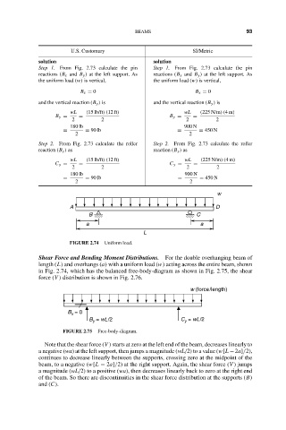
Shear Force and Bending Moment Distributions. For the double overhanging beam of
length (L) and overhangs (a) with a uniform load (w) acting across the entire beam, shown
in Fig. 2.74, which has the balanced free-body-diagram as shown in Fig. 2.75, the shear
force (V ) distribution is shown in Fig. 2.76.
w (force/length)
B = 0
x
B = wL/2 C = wL/2
y
y
FIGURE 2.75 Free-body-diagram.
Note that the shear force (V ) starts at zero at the left end of the beam, decreases linearly to
a negative (wa) at the left support, then jumps a magnitude (wL/2) to a value (w[L −2a]/2),
continues to decrease linearly between the supports, crossing zero at the midpoint of the
beam, to a negative (w[L − 2a]/2) at the right support. Again, the shear force (V ) jumps
a magnitude (wL/2) to a positive (wa), then decreases linearly back to zero at the right end
of the beam. So there are discontinuities in the shear force distribution at the supports (B)
and (C).