Page 106 - Marks Calculation for Machine Design
P. 106

P1: Sanjay
                          January 4, 2005
                 Brown˙C02
        Brown.cls
                  88
                            F
                                   a  16:18  STRENGTH OF MACHINES  a    F
                            A                                           D
                                     B                         C
                                                  L
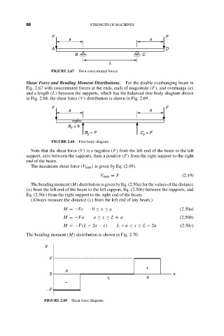
                            FIGURE 2.67  Twin concentrated forces.
                  Shear Force and Bending Moment Distributions.  For the double overhanging beam in
                  Fig. 2.67 with concentrated forces at the ends, each of magnitude (F), and overhangs (a)
                  and a length (L) between the supports, which has the balanced free-body-diagram shown
                  in Fig. 2.68, the shear force (V ) distribution is shown in Fig. 2.69.
                            F                                           F
                                   a                              a


                                  B  = 0
                                    x
                                         B  = F               C  = F
                                          y
                                                               y
                            FIGURE 2.68  Free-body-diagram.
                    Note that the shear force (V ) is a negative (F) from the left end of the beam to the left
                  support, zero between the supports, then a positive (F) from the right support to the right
                  end of the beam.
                    The maximum shear force (V max ) is given by Eq. (2.49).
                                               V max = F                       (2.49)
                    The bending moment (M) distribution is given by Eq. (2.50a) for the values of the distance
                  (x) from the left end of the beam to the left support, Eq. (2.50b) between the supports, and
                  Eq. (2.50c) from the right support to the right end of the beam.
                    (Always measure the distance (x) from the left end of any beam.)
                                 M =−Fx     0 ≤ x ≤ a                         (2.50a)
                                 M =−Fa     a ≤ x ≤ L + a                     (2.50b)
                                 M =−F(L + 2a − x)   L + a ≤ x ≤ L + 2a       (2.50c)

                  The bending moment (M) distribution is shown in Fig. 2.70.

                         V
                           F

                                                                 +
                                 a
                           0                                               x
                                                  L              a
                                 –
                          –F

                         FIGURE 2.69  Shear force diagram.
   101   102   103   104   105   106   107   108   109   110   111