
Page 102 - Marks Calculation for Machine Design
P. 102
P1: Sanjay
January 4, 2005
Brown˙C02
Brown.cls
84
U.S. Customary 16:18 STRENGTH OF MACHINES SI/Metric
Step 2. From Fig. 2.62, this maximum shear Step 2. Figure 2.62 shows that this maximum
force (V max ) occurs at the roller support. shear force (V max ) occurs at the roller support.
Step 3. Calculate the maximum bending Step 3. Calculate the maximum bending
moment (M max ) from Eq. (2.45) as moment (M max ) from Eq. (2.45) as
w w
2
2
M max = (L + a) (L − a) 2 M max = (L + a) (L − a) 2
8 L 2 8 L 2
(113 lb/ft) (1,540 N/m)
= =
8 (3ft) 2 8 (1m) 2
2
2
×(3ft + 1ft) (3ft − 1ft) 2 ×(1m + 0.3m) (1m − 0.3m) 2
(113 lb/ft) 2 2 (1,540 N/m) 2 2
= × (4ft) (2ft) = × (1.3m) (0.7m)
2
2
(72 ft ) (8m )
1.57 lb 2 2 192.5N 2 2
= (16 ft )(4ft ) = 3 (1.69 m )(0.49 m )
ft 3 m
= 100 ft · lb = 159 N · m
Step 4. The maximum bending moment Step 4. This maximum bending moment
(M max ) occurs at the location shown in Fig. 2.63 (M max ) occurs at the location shown in Fig. 2.63
and given by Eq. (2.46). and given by Eq. (2.46).
L a 2 L a 2
x M max = 1 − x M max = 1 −
2 L 2 2 L 2
3ft (1ft) 2 1m (0.3m) 2
= 1 − = 1 −
2 (3ft) 2 2 (1m) 2
2
1ft 2 8 0.09 m
= (1.5ft) 1 − = (1.5ft) = (0.5m) 1 − 2
9ft 2 9 1m
= (0.5m)(0.91) = 0.455 m
= 1.33 ft
w
B
A
∆ C
L a
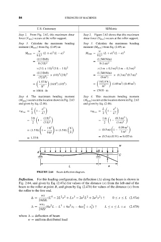
FIGURE 2.64 Beam deflection diagram.
Deflection. For this loading configuration, the deflection ( ) along the beam is shown in
Fig. 2.64, and given by Eq. (2.47a) for values of the distance (x) from the left end of the
beam to the roller at point B, and given by Eq. (2.47b) for values of the distance (x) from
the roller to the free end.
wx 4 2 2 3 2 2 2 2
= (L − 2L x + Lx − 2a L + 2a x ) ↑ 0 ≤ x ≤ L (2.47a)
24EIL
wx 1 2 3 2 2 3
= (4a L − L + 6a x 1 − 4ax + x ) ↑ L ≤ x ≤ L + a (2.47b)
1
1
24EI
where = deflection of beam
w = uniform distributed load