
Page 100 - Marks Calculation for Machine Design
P. 100
P1: Sanjay
January 4, 2005
16:18
Brown˙C02
Brown.cls
STRENGTH OF MACHINES
82
The bending moment distribution is given by Eq. (2.44a) for the values of the distance
(x) from the left end of the beam to the roller, and Eq. (2.44b) from the roller to the free
end. (Always measure the distance (x) from the left end of any beam.)
wx 2 2
M = (L − a − Lx) 0 ≤ x ≤ L (2.44a)
2L
w 2
M = (L + a − x) L ≤ x ≤ L + a (2.44b)
2
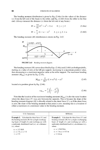
The bending moment (M) distribution is shown in Fig. 2.63.
M
(L/2)[1 – a 2 /L 2 ]
M max
+ + a
0 x
L – – L + a
(L)[1 – a 2 /L 2 ]
wa 2 /2
FIGURE 2.63 Bending moment diagram.
Thebendingmoment(M)curvesdescribedbyEqs.(2.44a)and(2.44b)arebothparabolic,
starting at a value of zero at the left pin support, increasing to a maximum positive value,
then decreasing to a maximum negative value at the roller support. The maximum bending
moment (M max ) is given by Eq. (2.45),
w 2 2
M max = 2 (L + a) (L − a) (2.45)
8L
located at a position given by Eq. (2.46).
L a 2
= 1 − (2.46)
x M max 2
2 L
Note that the location of the maximum bending moment (M max ) is also the same location
where the shear force (V ) was zero between the supports. This is because the slope of the
bending moment diagram (M) is directly related to the shear force (V ), so if the shear force
is zero, the slope of the bending moment at that point is zero, meaning this is a location of
either a maximum or a minimum value in the bending moment.
U.S. Customary SI/Metric
Example 2. Calculate the shear force (V ) and Example 2. Calculate the shear force (V ) and
the bending moment (M) for a single overhang- bending moment (M) for a single overhanging
ing beam of length (L) and overhang (a) with beam of length (L) and overhang (a) with a
a uniformly distributed load (w), at a distance uniformly distributed load (w), at a distance (x),
(x), where where
w = 113 lb/ft w = 1,540 N/m
L = 3 ft, a = 1ft L = 1m, a = 0.3 m
x = 2ft x = 0.6 m