
Page 105 - Marks Calculation for Machine Design
P. 105
P1: Sanjay
January 4, 2005
Brown˙C02
Brown.cls
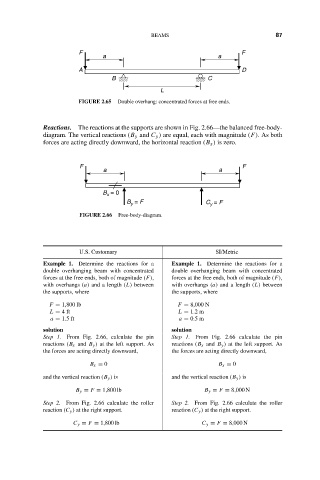
F
a 16:18 BEAMS a F 87
A D
B C
L
FIGURE 2.65 Double overhang: concentrated forces at free ends.
Reactions. The reactions at the supports are shown in Fig. 2.66—the balanced free-body-
diagram. The vertical reactions (B y and C y ) are equal, each with magnitude (F). As both
forces are acting directly downward, the horizontal reaction (B x ) is zero.
F F
a a
B = 0
x
B = F C = F
y
y
FIGURE 2.66 Free-body-diagram.
U.S. Customary SI/Metric
Example 1. Determine the reactions for a Example 1. Determine the reactions for a
double overhanging beam with concentrated double overhanging beam with concentrated
forces at the free ends, both of magnitude (F), forces at the free ends, both of magnitude (F),
with overhangs (a) and a length (L) between with overhangs (a) and a length (L) between
the supports, where the supports, where
F = 1,800 lb F = 8,000 N
L = 4ft L = 1.2 m
a = 1.5 ft a = 0.5 m
solution solution
Step 1. From Fig. 2.66, calculate the pin Step 1. From Fig. 2.66 calculate the pin
reactions (B x and B y ) at the left support. As reactions (B x and B y ) at the left support. As
the forces are acting directly downward, the forces are acting directly downward,
B x = 0 B x = 0
and the vertical reaction (B y ) is and the vertical reaction (B y ) is
B y = F = 1,800 lb B y = F = 8,000 N
Step 2. From Fig. 2.66 calculate the roller Step 2. From Fig. 2.66 calculate the roller
reaction (C y ) at the right support. reaction (C y ) at the right support.
C y = F = 1,800 lb C y = F = 8,000 N