
Page 108 - Marks Calculation for Machine Design
P. 108
P1: Sanjay
January 4, 2005
Brown˙C02
Brown.cls
90
U.S. Customary 16:18 STRENGTH OF MACHINES SI/Metric
solution solution
Step 1. Calculate the maximum shear force Step 1. Calculate the maximum shear force
(V max ) from Eq. (2.49) as (V max ) from Eq. (2.49) as
V max = F = 1,800 lb V max = F = 8,000 N
Step 2. From Fig. 2.69, the maximum shear Step 2. From Fig. 2.69, the maximum shear
force (V max ) occurs in two regions, one from force (V max ) occurs in two regions, one from
the left end of the beam to the left support, and the left end of the beam to the left support, and
the other from the right support to the right end the other from the right support to the right end
of the beam. of the beam.
Step 3. Calculate the maximum bending Step 3. Calculate the maximum bending
moment (M max ) from Eq. (2.51). moment (M max ) from Eq. (2.51).
M max = Fa = (1,800 lb)(1.5ft) M max = Fa = (8,000 N)(0.5m)
= 2,700 ft · lb = 4,000 N · m
Step 4. From Fig. 2.70, the maximum bending Step 4. From Fig. 2.70, the maximum bending
moment (M max ) occurs in the region between moment (M max ) occurs in the region between
the two forces. the two forces.
F F
a ∆ Mid a
A D
∆ Tip B C
L
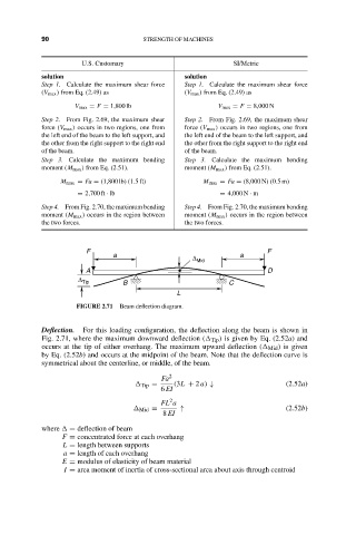
FIGURE 2.71 Beam deflection diagram.
Deflection. For this loading configuration, the deflection along the beam is shown in
Fig. 2.71, where the maximum downward deflection ( Tip ) is given by Eq. (2.52a) and
occurs at the tip of either overhang. The maximum upward deflection ( Mid ) is given
by Eq. (2.52b) and occurs at the midpoint of the beam. Note that the deflection curve is
symmetrical about the centerline, or middle, of the beam.
Fa 2
Tip = (3L + 2 a) ↓ (2.52a)
6 EI
2
FL a
Mid = ↑ (2.52b)
8 EI
where = deflection of beam
F = concentrated force at each overhang
L = length between supports
a = length of each overhang
E = modulus of elasticity of beam material
I = area moment of inertia of cross-sectional area about axis through centroid