
Page 107 - Marks Calculation for Machine Design
P. 107
P1: Sanjay
January 4, 2005
16:18
Brown.cls
Brown˙C02
M
a BEAMS L + a L + 2a 89
0 x
– – –
–Fa
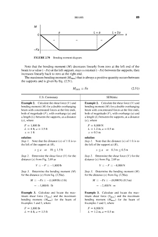
FIGURE 2.70 Bending moment diagram.
Note that the bending moment (M) decreases linearly from zero at the left end of the
beam to a value (−Fa) at the left support, stays a constant (−Fa) between the supports, then
increases linearly back to zero at the right end.
The maximum bending moment (M max ) that is always a positive quantity occurs between
the supports and is given by Eq. (2.51).
M max = Fa (2.51)
U.S. Customary SI/Metric
Example 2. Calculate the shear force (V ) and Example 2. Calculate the shear force (V ) and
bending moment (M) for a double overhanging bending moment (M) for a double overhanging
beam with concentrated forces at the free ends, beam with concentrated forces at the free ends,
both of magnitude (F), with overhangs (a) and both of magnitude (F), with overhangs (a) and
a length (L) between the supports, at a distance a length (L) between the supports, at a distance
(x), where (x), where
F = 1,800 lb F = 8,000 N
L = 4 ft, a = 1.5 ft L = 1.2 m, a = 0.5 m
x = 1ft x = 0.3 m
solution solution
Step 1. Note that the distance (x) of1ftisto Step 1. Note that the distance (x) of1ftisto
the left of the support at (B), the left of the support at (B),
x ≤ a or 1ft ≤ 1.5ft x ≤ a or 0.3m ≤ 0.5m
Step 2. Determine the shear force (V ) for the Step 2. Determine the shear force (V ) for the
distance (x) from Fig. 2.69 as distance (x) from Fig. 2.69 as
V =−F =−1,800 lb V =−F =−8,000 N
Step 3. Determine the bending moment (M) Step 3. Determine the bending moment (M)
for the distance (x) from Eq. (2.50a). for the distance (x) from Eq. (2.50a).
M =−Fx =−(1,800 lb)(1ft) M =−Fx =−(8,000 N)(0.3m)
=−1,800 ft · lb =−2,400 N · m
Example 3. Calculate and locate the max- Example 3. Calculate and locate the max-
imum shear force (V max ) and the maximum imum shear force (V max ) and the maximum
bending moment (M max ) for the beam of bending moment (M max ) for the beam of
Examples 1 and 2, where Examples 1 and 2, where
F = 1,800 lb F = 8,000 N
L = 4 ft, a = 1.5 ft L = 1.2 m, a = 0.5 m